Passive Components Blog
No Result
View All Result
  • Home
  • NewsFilter
    • All
    • Aerospace & Defence
    • Antenna
    • Applications
    • Automotive
    • Capacitors
    • Circuit Protection Devices
    • electro-mechanical news
    • Filters
    • Fuses
    • Inductors
    • Industrial
    • Integrated Passives
    • inter-connect news
    • Market & Supply Chain
    • Market Insights
    • Medical
    • Modelling and Simulation
    • New Materials & Supply
    • New Technologies
    • Non-linear Passives
    • Oscillators
    • Passive Sensors News
    • Resistors
    • RF & Microwave
    • Telecommunication
    • Weekly Digest

    EMC‑Compliant PCB and Connector Design Guidelines

    Practical Value of Structural Diagnostics for Tantalum Capacitor Anodes

    Hall-Effect Sensing for Harsh Environments: TT Electronics Selected in NASA’s Dragonfly Fan

    Bourns Releases Automotive Gate Driver Transformer for Isolated Power

    Stackpole Releases High-Frequency Thin Film Chip Resistors for RF up to 50 GHz

    Knowles Expands High‑Q Ceramic Core Inductors for RF designs

    Vishay Unveils 1.5 kV IHDV High Voltage Power Inductors for EV and Industrial Converters

    SCHURTER Introduces PPTC Resettable Overcurrent Protection for Compact Electronics

    TrendForce: CSP in‑house AI ASIC Boom Reshapes Capacitor Demand

    Trending Tags

    • Ripple Current
    • RF
    • Leakage Current
    • Tantalum vs Ceramic
    • Snubber
    • Low ESR
    • Feedthrough
    • Derating
    • Dielectric Constant
    • New Products
    • Market Reports
  • VideoFilter
    • All
    • Antenna videos
    • Capacitor videos
    • Circuit Protection Video
    • Filter videos
    • Fuse videos
    • Inductor videos
    • Inter-Connect Video
    • Non-linear passives videos
    • Oscillator videos
    • Passive sensors videos
    • Resistor videos

    EMC‑Compliant PCB and Connector Design Guidelines

    Why Isolated DC/DC Power Supplies Fail Late, Würth Elektronik Podcast

    Designing 800 V DC EMC Filters: Calculation, Simulation and Measurement

    Current Sense Transformer Datasheet and Design‑in Guide

    Designing a USB Type‑C Flyback Planar Transformer with Frenetic’s Planar Tool

    Magnetics Design in High‑Frequency GaN Converters

    Qi2 Wireless Charging: Inductors, Capacitors and EMC Filters

    Two‑capacitor paradox explained for engineers

    Capacitances of Nonlinear MLCCs: What Datasheets Don’t Tell You

    Trending Tags

    • Capacitors explained
    • Inductors explained
    • Resistors explained
    • Filters explained
    • Application Video Guidelines
    • EMC
    • New Products
    • Ripple Current
    • Simulation
    • Tantalum vs Ceramic
  • Knowledge Blog
  • DossiersNew
  • Suppliers
    • Who is Who
  • PCNS
    • PCNS 2025
    • PCNS 2023
    • PCNS 2021
    • PCNS 2019
    • PCNS 2017
  • Events
No Result
View All Result
Passive Components Blog
No Result
View All Result

Sumida Releases New Metal Compound Molding Power Inductors

18.6.2019
Reading Time: 2 mins read
A A

Source: Sumida news

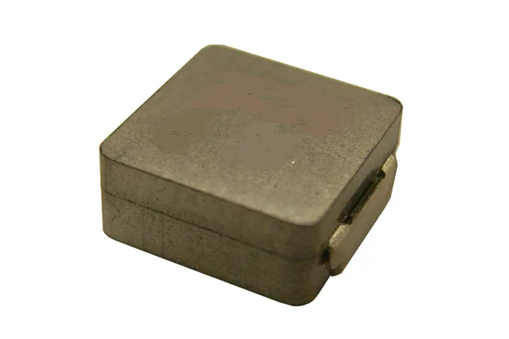
Further to the addition of 0530CDMCC/DS and 0420CDMCC/DS, 0315CDMCC/DS (3.7×3.4×1.5mm Max.) and 0320CDMCC/DS (3.7×3.4×2.0mm Max.) are newly added to the CDMC series as the Metal Compound Molding Type Inductors.

RelatedPosts

EMC‑Compliant PCB and Connector Design Guidelines

Practical Value of Structural Diagnostics for Tantalum Capacitor Anodes

Hall-Effect Sensing for Harsh Environments: TT Electronics Selected in NASA’s Dragonfly Fan

Metal compound molding construction is used in the CDMC series to achieve high electric performance and high magnetic shielding, and aslo bring low audible core noise, low profile and high current performance.

Key Features:

  • Magnetically shielded
  • Operating temperature range: -55℃~+125℃ (including coil’s self temperature rise)

Applications:

Ideally used in notebook, ultrabook, tablet PC, LCD display, server application; HDD,SSD modules application; Low profile, high current power supplies; Battery powered devices; High current, POL converters; DC/DC converter in distributed power systems

Parts List (0315CDMCC/DS):

Part Name Inductance [Within] (μH) ※1 D.C.R. at 20℃ (A) Max. (Typ.) (mΩ) Saturation Current (A) Max.(Typ.) ※2 Temperature Rise Currrent
(A) ※3
0315CDMCCDS-R56MC 0.56 ± 20% 25.00 (20.50) 5.20 (6.10) (5.50)
0315CDMCCDS-R82MC 0.82 ± 20% 32.00 (26.50) 4.20 (4.90) (5.00)
0315CDMCCDS-1R0MC 1.00 ± 20% 41.00 (34.00) 4.10 (4.80) (4.30)
0315CDMCCDS-1R5MC 1.50 ± 20% 65.00 (53.50) 3.40 (4.00) (3.50)
0315CDMCCDS-2R2MC 2.20 ± 20% 94.00 (78.00) 3.60 (4.30) (2.80)
0315CDMCCDS-3R3MC 3.30 ± 20% 123 (102.50) 1.90 (2.20) (2.50)
0315CDMCCDS-4R7MC 4.70 ± 20% 199 (166) 1.90 (2.30) (1.80)

Parts List (0320CDMCC/DS):

Part Name Inductance [Within] (μH) ※1 D.C.R. at 20℃ (A) Max. (Typ.) (mΩ) Saturation Current (A) Max.(Typ.) ※2 Temperature Rise Currrent
(A) ※3
0320CDMCCDS-R22MC 0.22 ± 20% 10.20 (8.50) 6.90 (8.10) (10.00)
0320CDMCCDS-R33MC 0.33 ± 20% 11.40 (9.50) 6.50 (7.60) (9.50)
0320CDMCCDS-R47MC 0.47 ± 20% 15.60 (13.00) 5.20 (6.20) (7.50)
0320CDMCCDS-R56MC 0.56 ± 20% 18.00 (15.00) 4.80 (5.70) (7.00)
0320CDMCCDS-R68MC 0.68 ± 20% 21.60 (18.00) 4.60 (5.40) (6.50)
0320CDMCCDS-1R0MC 1.00 ± 20% 31.20 (26.00) 4.40 (5.20) (5.50)
0320CDMCCDS-1R5MC 1.50 ± 20% 45.60 (38.00) 3.20 (3.80) (4.00)
0320CDMCCDS-2R2MC 2.20 ± 20% 72.00 (60.00) 2.90 (3.40) (3.50)
0320CDMCCDS-3R3MC 3.30 ± 20% 108 (90.00) 2.10 (2.50) (2.50)

※1 Measuring frequency inductance at 100KHz, 1.0V
※2 Saturation current: The actual value of DC current when the inductance is over 70% of the initial value.
※3 Temperature rise current: The actual value of DC current when the coil temperature rise is △T=40℃. △T=40℃ (Ta=25℃) Board conditions: FR4, Copper=70μm, four-layer PWB, t=1.6mm.

Production Stage:

In mass production

Related

Recent Posts

Bourns Releases Automotive Gate Driver Transformer for Isolated Power

22.6.2026
7

Knowles Expands High‑Q Ceramic Core Inductors for RF designs

19.6.2026
17

Vishay Unveils 1.5 kV IHDV High Voltage Power Inductors for EV and Industrial Converters

19.6.2026
25

SCHURTER Introduces PPTC Resettable Overcurrent Protection for Compact Electronics

18.6.2026
27

Samsung Presents Ultra‑Thin Silicon Capacitors for AI and Server PDN

17.6.2026
54

YAGEO Introduces 310VAC SMD Y2 Safety MP Capacitors for Compact EMI Filtering

16.6.2026
32

DMASS: European Components Distribution Returns To Growth In Q1 2026

16.6.2026
50

German Component Distribution Market Rebounds in Q1 2026 According to FBDi

16.6.2026
35

Nippon Chemi-Con Announces New Capacitor series for AI, Automotive and Immersion Cooling

16.6.2026
61

Upcoming Events

Jun 30
17:00 - 18:00 CEST

PSMA Capacitor Committee Webinar: High Voltage Pulse Capacitors

Jul 14
16:00 - 17:00 CEST

EMC Design Essentials: Mastering Varistors and Common Mode Chokes

Jul 21
16:00 - 17:00 CEST

Safety by design: X and Y Interference suppression capacitors for power line filters

View Calendar

Popular Posts

  • Boost Converter Design and Calculation

    0 shares
    Share 0 Tweet 0
  • Buck Converter Design and Calculation

    0 shares
    Share 0 Tweet 0
  • Flyback Converter Design and Calculation

    0 shares
    Share 0 Tweet 0
  • LLC Resonant Converter Design and Calculation

    0 shares
    Share 0 Tweet 0
  • MLCC and Ceramic Capacitors

    0 shares
    Share 0 Tweet 0
  • Earthing Systems and IEC Classification Explained

    0 shares
    Share 0 Tweet 0
  • Dual Active Bridge (DAB) Topology

    0 shares
    Share 0 Tweet 0
  • SEPIC Converter Design and Calculation

    0 shares
    Share 0 Tweet 0
  • Nvidia Vera Rubin: Why One AI Rack Needs So Many More MLCC Capacitors

    0 shares
    Share 0 Tweet 0
  • MLCC Case Sizes Standards Explained

    0 shares
    Share 0 Tweet 0

Newsletter Subscription


Passive Components Blog

© EPCI - Leading Passive Components Educational and Information Site

  • Home
  • Privacy Policy
  • EPCI Membership & Advertisement
  • About

No Result
View All Result
  • Home
  • Knowledge Blog
  • Dossiers
  • PCNS

© EPCI - Leading Passive Components Educational and Information Site

This website uses cookies. By continuing to use this website you are giving consent to cookies being used. Visit our Privacy and Cookie Policy.
Go to mobile version