Passive Components Blog
No Result
View All Result
  • Home
  • NewsFilter
    • All
    • Aerospace & Defence
    • Antenna
    • Applications
    • Automotive
    • Capacitors
    • Circuit Protection Devices
    • electro-mechanical news
    • Filters
    • Fuses
    • Inductors
    • Industrial
    • Integrated Passives
    • inter-connect news
    • Market & Supply Chain
    • Market Insights
    • Medical
    • Modelling and Simulation
    • New Materials & Supply
    • New Technologies
    • Non-linear Passives
    • Oscillators
    • Passive Sensors News
    • Resistors
    • RF & Microwave
    • Telecommunication
    • Weekly Digest

    SCHURTER Unveils High Voltage Fuses for EV Applications

    YAGEO Releases First to Market 750V Aluminum Capacitors

    binder Introduces M9 Compact Circular Connector

    Smolteks CNF-MIM Capacitors Meet Thermal and Voltage Stability Industry Requirements

    Wk 26 Electronics Supply Chain Digest

    Learn How Supercapacitors Enhance Power System in Knowles eBook

    TDK Releases Industry First 1uF 100V X7R MLCCs in 1608 Case

    YAGEO Expands One Turn Inductors for AI and High-Efficiency Power Applications

    YAGEO Extends Lifetime of its Aluminum SMD Chip Capacitors to 5500hrs at 125C/Ur

    Trending Tags

    • Ripple Current
    • RF
    • Leakage Current
    • Tantalum vs Ceramic
    • Snubber
    • Low ESR
    • Feedthrough
    • Derating
    • Dielectric Constant
    • New Products
    • Market Reports
  • VideoFilter
    • All
    • Antenna videos
    • Capacitor videos
    • Circuit Protection Video
    • Filter videos
    • Fuse videos
    • Inductor videos
    • Inter-Connect Video
    • Non-linear passives videos
    • Oscillator videos
    • Passive sensors videos
    • Resistor videos

    Accelerating Full Bridge LLC Resonant Converter Design with Frenetic AI

    Understanding Switched Capacitor Converters

    Coupled Inductors Circuit Model and Examples of its Applications

    Inductor Resonances and its Impact to EMI

    Highly Reliable Flex Rigid PCBs, Würth Elektronik Webinar

    Causes of Oscillations in Flyback Converters

    How to design a 60W Flyback Transformer

    Modeling and Simulation of Leakage Inductance

    Power Inductor Considerations for AI High Power Computing – Vishay Video

    Trending Tags

    • Capacitors explained
    • Inductors explained
    • Resistors explained
    • Filters explained
    • Application Video Guidelines
    • EMC
    • New Products
    • Ripple Current
    • Simulation
    • Tantalum vs Ceramic
  • Knowledge Blog
  • Suppliers
    • Who is Who
  • Events
No Result
View All Result
Passive Components Blog
No Result
View All Result

Tantalum Capacitor Wet Test: Method Limitations and Sensitivity for Tantalum Powder Control

20.1.2025
Reading Time: 5 mins read
A A

This article by Dr. V. Azbel, an Independent consultant on tantalum capacitors, discusses the wet test method limitations for evaluating of the stability and quality of tantalum capacitor anodes and tantalum powder.

Introduction

RelatedPosts

Enhanced Process Control in Tantalum Capacitor Anode Manufacturing Reduces Cost and Improves Reliability

Enhancing Effectiveness of Tantalum Capacitor Anode Control

Risk of Tantalum Capacitor Anode Overheating: Modeling and Practical Solutions

The wet test is a widely used method for incoming powder control. It assesses the acceptability of powders based on key electrical parameters of anodes, such as capacitance and leakage currents. This testing methodology involves manufacturing control anodes through an identical process by both the powder supplier and the customer. The only variable in this process is the powder itself.

For control purposes, a porous sintered pellet with a predefined porosity and neck size is produced from the powder. This pellet is then used to manufacture anodes with the required capacitance and leakage current characteristics.

However, the wet test has several limitations that can complicate the assessment of powder acceptability. Firstly, it has limited sensitivity, which can make it difficult to detect even small deviations in the powder’s properties. Secondly, the anode’s capacitance is primarily determined by the surface area of the pellet’s porous structure and the dielectric constant of amorphous Ta₂O₅. This means that capacitance is not influenced by factors that are critical to leakage currents, such as neck size, internal stresses, and defects. Thirdly, even when the powder parameters meet the specifications, they can be at the edge of acceptable values. Such deviations may be insignificant for capacitance but critical for leakage currents. Fourthly, the distribution of powder particle sizes, which affects porosity and neck size during sintering, is significant for maintaining stable leakage currents.

Problem Description

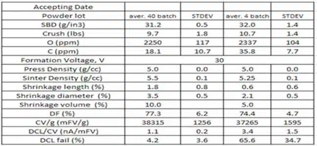
An issue was identified during operation: after 40 stable powder batches, the following four batches exhibited a sharp increase in failures caused by leakage current (DCL) spikes, despite the powders meeting specifications (see table).

Analysis:

The analysis revealed the following:

  • Problematic batches exhibited lower shrinkage values, while the coefficient of variation (CV/g) values, which are related to the porosity of the sintered pellet, remained relatively unchanged.
  • Despite this, the frequency of leakage current failures increased. Potential causes could include variations in the neck size, internal stresses, and defects in the porous structure of the sintered pellet.

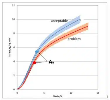
To determine the key factor influencing the porous structure of the sintered pellet in the problematic batches, a mechanical testing method was employed. This method involved compressing sintered pellets while simultaneously recording a “stress-strain” curve.

Characteristics derived from the “stress-strain” curve enable the evaluation of changes in the porosity and defectiveness of the sintered pellet (see Appendix). By comparing the curve characteristics for pellets produced from acceptable and problematic batches, structural differences can be identified.

Figure 1 presents the “stress-strain” curves for powders obtained from acceptable (blue line) and problematic (red line) batches.

Analysis Results:

  • The curve analysis revealed a significant reduction in yield strength (Ay) by more than 30% in problematic batches.
  • There was a decrease in elastic modulus (E) by approximately 10–15%.
  • The strain hardening coefficient (n) remained practically unchanged.

The decrease in Ay indicates a smaller neck size in the porous structure of problematic batches, which critically impacts leakage currents under identical formation voltage. The decrease in E aligns with a reduction in CV/g, while minor changes in n suggest a similar level of defectiveness.

Conclusions:

The analysis of mechanical and electrical tests suggests that the primary cause of problematic batches is likely related to changes in the particle size distribution curve of the powder, rather than internal stresses or defects in the sintered pellet. The particle size distribution curve is the final step in powder production and has a more direct and significant impact on neck size, which, in turn, affects anode characteristics during incoming inspection control.

This method demonstrated higher sensitivity compared to the wet test, enabling a clearer correlation between powder characteristics and final product quality to be established.

Recommendations:

Incorporate mechanical testing into the standard quality control procedures for powders.

APPENDIX

Strain-Stress curve parameters description for porous materials:

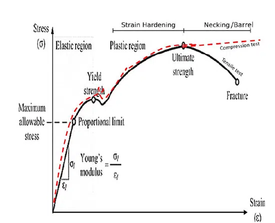
1. **Yield Strength (Ay):** The yield strength of a porous material depends on the size of its neck, which impacts the maximum permissible formation voltage. For porous materials, the yield stress can be calculated using the following equation: Ay = b*A0*(X/D)^2, where:

  • b is an empirical constant
  • Ay is the yield point of the sintered porous material
  • A0 is the yield point of the deformed material
  • X is the neck size (divided by the primary powder particle size, D)
  • The ratio X/D cannot exceed 0.5

2. **Young’s Modulus (E):** Young’s modulus is related to porosity and affects capacitance. The behavior of Young’s modulus for a porous material can be described using the following equation: E = E0 (1-p/pc), where:

  • E is the elastic modulus of a porous material with a porosity of p
  • E0 is the modulus of a solid material at a density pc ~ 1

3. **CC Curve:** The CC curve can be used to calculate the strain hardening coefficient (n), which is related to the material’s defectiveness. This coefficient can influence leakage currents at the anode.

Related

Source: Vladimir Azbel

Recent Posts

YAGEO Releases First to Market 750V Aluminum Capacitors

30.6.2025
5

Smolteks CNF-MIM Capacitors Meet Thermal and Voltage Stability Industry Requirements

30.6.2025
3

Learn How Supercapacitors Enhance Power System in Knowles eBook

30.6.2025
2

TDK Releases Industry First 1uF 100V X7R MLCCs in 1608 Case

27.6.2025
9

YAGEO Extends Lifetime of its Aluminum SMD Chip Capacitors to 5500hrs at 125C/Ur

27.6.2025
13

Murata Releases Worlds First 10µF/50V Automotive MLCC in 0805 Size

26.6.2025
40

Advancements and Applications of Switch Capacitor Power Converters

25.6.2025
24

Accelerating Full Bridge LLC Resonant Converter Design with Frenetic AI

24.6.2025
14

Samsung Delivers Silicon Capacitors to Marwell AI Systems

24.6.2025
48

Smolteks CNF MIM Capacitor Break 1 µF/mm²

19.6.2025
36

Upcoming Events

Jul 23
13:00 - 14:00 CEST

PCB design for a Smartwatch

View Calendar

Popular Posts

  • Buck Converter Design and Calculation

    0 shares
    Share 0 Tweet 0
  • Boost Converter Design and Calculation

    0 shares
    Share 0 Tweet 0
  • Flyback Converter Design and Calculation

    0 shares
    Share 0 Tweet 0
  • What is a Dielectric Constant and DF of Plastic Materials?

    4 shares
    Share 4 Tweet 0
  • LLC Resonant Converter Design and Calculation

    0 shares
    Share 0 Tweet 0
  • Ripple Current and its Effects on the Performance of Capacitors

    3 shares
    Share 3 Tweet 0
  • How to Design an Inductor

    0 shares
    Share 0 Tweet 0
  • Dual Active Bridge (DAB) Topology Explained

    0 shares
    Share 0 Tweet 0
  • SEPIC Converter Design and Calculation

    0 shares
    Share 0 Tweet 0
  • Why Low ESR Matters in Capacitor Design

    0 shares
    Share 0 Tweet 0

Newsletter Subscription


Passive Components Blog

© EPCI - Leading Passive Components Educational and Information Site

  • Home
  • Privacy Policy
  • EPCI Membership & Advertisement
  • About

No Result
View All Result
  • Home
  • Knowledge Blog
  • Premium Suppliers

© EPCI - Leading Passive Components Educational and Information Site

This website uses cookies. By continuing to use this website you are giving consent to cookies being used. Visit our Privacy and Cookie Policy.
Go to mobile version