Passive Components Blog
No Result
View All Result
  • Home
  • NewsFilter
    • All
    • Aerospace & Defence
    • Antenna
    • Applications
    • Automotive
    • Capacitors
    • Circuit Protection Devices
    • electro-mechanical news
    • Filters
    • Fuses
    • Inductors
    • Industrial
    • Integrated Passives
    • inter-connect news
    • Market & Supply Chain
    • Market Insights
    • Medical
    • Modelling and Simulation
    • New Materials & Supply
    • New Technologies
    • Non-linear Passives
    • Oscillators
    • Passive Sensors News
    • Resistors
    • RF & Microwave
    • Telecommunication
    • Weekly Digest

    Vishay Releases Industry First Automotive SMD Y1 Safety Ceramic Capacitors

    Researchers Enhanced 2D Ferromagnets Performance

    Bourns Releases Two High Current Common Mode Choke Models

    Electronics Weekly Announcing Finalists for Elektra Awards 2025

    Exxelia Exhibit at Electronica India September 17–19, 2025

    Würth Elektronik Announces 2025 Digital WE Days Virtual Conference

    VINATech Unveils Hybrid Energy Storage System to Revolutionize Grid Stability and Power Delivery

    SCHURTER Releases High Performance EV-Fuse

    Panasonic Industry to Double Production of MEGTRON PCB Materials

    Trending Tags

    • Ripple Current
    • RF
    • Leakage Current
    • Tantalum vs Ceramic
    • Snubber
    • Low ESR
    • Feedthrough
    • Derating
    • Dielectric Constant
    • New Products
    • Market Reports
  • VideoFilter
    • All
    • Antenna videos
    • Capacitor videos
    • Circuit Protection Video
    • Filter videos
    • Fuse videos
    • Inductor videos
    • Inter-Connect Video
    • Non-linear passives videos
    • Oscillator videos
    • Passive sensors videos
    • Resistor videos

    Ripple Steering in Coupled Inductors: SEPIC Case

    SEPIC Converter with Coupled and Uncoupled Inductors

    Coupled Inductors in SEPIC versus Flyback Converters

    Non-Linear MLCC Class II Capacitor Measurements Challenges

    Percolation Phenomenon and Reliability of Molded Power Inductors in DC/DC converters

    Root Causes and Effects of DC Bias and AC in Ceramic Capacitors

    How to Calculate the Output Capacitor for a Switching Power Supply

    Switched Capacitor Converter Explained

    Understanding Inductor Dot Markings and Their Application in LTspice

    Trending Tags

    • Capacitors explained
    • Inductors explained
    • Resistors explained
    • Filters explained
    • Application Video Guidelines
    • EMC
    • New Products
    • Ripple Current
    • Simulation
    • Tantalum vs Ceramic
  • Knowledge Blog
  • Suppliers
    • Who is Who
  • Events
No Result
View All Result
Passive Components Blog
No Result
View All Result

TDK EMC components and inductors: First chip beads and inductors with robust soft termination

21.3.2017
Reading Time: 2 mins read
A A

source: TDK news

TDK Corporation presents the world’s first multilayer chip beads and inductors with the innovative soft-termination technology that is already proven in TDK MLCCs. The external electrodes of the new KMZ1608 and KPZ1608 series of chip beads and the KLZ1608 and KLZ2012 series of inductors feature a conductive resin layer that offers effective protection against board flexure and solder cracks due to mechanical stress during mounting and thermal shock during operation. As a result, these soft-termination automotive-grade components offer high reliability under harsh conditions, even at high operating temperatures up to 150 °C. They are thus suitable for demanding automotive applications, such as engine control modules (ECMs) and various in-vehicle electronic control units (ECUs), and advanced driver assistance systems (ADAS), as well as in a variety of industrial equipment.

RelatedPosts

Vishay Releases Industry First Automotive SMD Y1 Safety Ceramic Capacitors

Researchers Enhanced 2D Ferromagnets Performance

Bourns Releases Two High Current Common Mode Choke Models

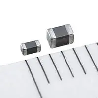
The demand for compact, lightweight and robust multilayer inductive components is steadily growing as the electronic functionality of vehicles continues to increase and as more and more ECUs are positioned closer to the engine. The new KMZ1608 and KPZ1608 series of chip beads are available in IEC 1608 case size with dimensions of 1.6 mm x 0.8 mm x 0.8 mm. The KLZ1608 and KLZ2012 series are available in IEC 1608 and 2012 case sizes and measure in at 1.6 mm x 0.8 mm x 0.8 mm and 2.0 mm x 1.25 mm x 1.25 mm, respectively. The lineup of multilayer chip beads and inductors with soft terminations will be continuously expanded to include smaller case sizes. Volume production of the AEC-Q200 qualified products began in March 2017.

Glossary

Soft termination: The terminal electrode of standard products consists of three layers: copper (Cu), nickel (Ni), and tin (Sn) on the base electrode of Ag. The terminal electrode of soft-termination components consists of two layers: Ni and Sn bonded to the Ag base electrode with an elastic resin.

Main applications

  • Engine control modules (ECM) and various in-vehicle electronic control units (ECU)
  • Advanced driver assistance systems (ADAS)
  • Industrial equipment

Main features and benefits

  • Effective protection against board flexure and solder cracks
  • Suitable for high operating temperatures up to 150 °C

Key data

Chip beads
Series Impedance [Ω]
@ 100 MHz, ±25%
DC resistance
[Ω] max.
Rated current [mA] max.
-55 to +125 °C +125 to +150 °C
KMZ1608
(signal lines)
50 to 2500 0.1 to 0.8 200 to 800 100 to 400
-55 to +85 °C +125 °C +150 °C
KPZ1608
(power lines)
30 to 1000 0.015 to 0.3 800 to 5000 500 to 2000 300 to 1000


Inductors
Series Inductance
[µH] ±20%
DC resistance
[Ω] ±30%
Rated current [mA] max.
KLZ1608 1.0 to 22 0.15 to 2.4 55 to 190
KLZ2012 1.0 to 100 0.10 to 3.7 30 to 700

Related

Recent Posts

Vishay Releases Industry First Automotive SMD Y1 Safety Ceramic Capacitors

17.9.2025
2

Researchers Enhanced 2D Ferromagnets Performance

16.9.2025
5

Bourns Releases Two High Current Common Mode Choke Models

16.9.2025
8

Electronics Weekly Announcing Finalists for Elektra Awards 2025

16.9.2025
7

Exxelia Exhibit at Electronica India September 17–19, 2025

15.9.2025
28

Würth Elektronik Announces 2025 Digital WE Days Virtual Conference

15.9.2025
11

VINATech Unveils Hybrid Energy Storage System to Revolutionize Grid Stability and Power Delivery

15.9.2025
18

SCHURTER Releases High Performance EV-Fuse

15.9.2025
6

5th PCNS Awards Outstanding Passive Component Papers

17.9.2025
61

TDK Releases Ultra-small PFC Capacitors

10.9.2025
35

Upcoming Events

Sep 22
September 22 @ 13:00 - September 25 @ 15:15 EDT

Pre Cap Visual Inspection per Mil-Std-883 (TM 2017)

Sep 30
September 30 @ 12:00 - October 2 @ 14:00 EDT

MIL-Std-883 TM 2010

Oct 17
12:00 - 14:00 EDT

External Visual Inspection per MIL-STD-883 TM 2009

Oct 20
October 20 - October 23

Digital WE Days 2025 – Virtual Conference

Oct 21
October 21 @ 12:00 - October 23 @ 14:15 EDT

Space and Military Standards for Hybrids and RF Microwave Modules

View Calendar

Popular Posts

  • Buck Converter Design and Calculation

    0 shares
    Share 0 Tweet 0
  • Boost Converter Design and Calculation

    0 shares
    Share 0 Tweet 0
  • Flyback Converter Design and Calculation

    0 shares
    Share 0 Tweet 0
  • LLC Resonant Converter Design and Calculation

    0 shares
    Share 0 Tweet 0
  • Dual Active Bridge (DAB) Topology Explained

    0 shares
    Share 0 Tweet 0
  • Ripple Current and its Effects on the Performance of Capacitors

    3 shares
    Share 3 Tweet 0
  • What is a Dielectric Constant and DF of Plastic Materials?

    4 shares
    Share 4 Tweet 0
  • SEPIC Converter Design and Calculation

    0 shares
    Share 0 Tweet 0
  • How to Design an Inductor

    0 shares
    Share 0 Tweet 0
  • Core Materials, Permeability and Their Losses

    0 shares
    Share 0 Tweet 0

Newsletter Subscription


Passive Components Blog

© EPCI - Leading Passive Components Educational and Information Site

  • Home
  • Privacy Policy
  • EPCI Membership & Advertisement
  • About

No Result
View All Result
  • Home
  • Knowledge Blog
  • Premium Suppliers

© EPCI - Leading Passive Components Educational and Information Site

This website uses cookies. By continuing to use this website you are giving consent to cookies being used. Visit our Privacy and Cookie Policy.
Go to mobile version