


As the electrification of the automotive progresses, the demand for motor generators is on the rise. There is also a trend towards integration of electric motors and inverters, and the requirements with regard to compact dimensions and resistance against heat and vibrations are becoming ever more severe, while high reliability is also an important factor. In some cases, wiring inductance can lead to high surge voltages which requires countermeasures such as suitable wiring design and snubber capacitors. At the same time, noise countermeasures are also essential.
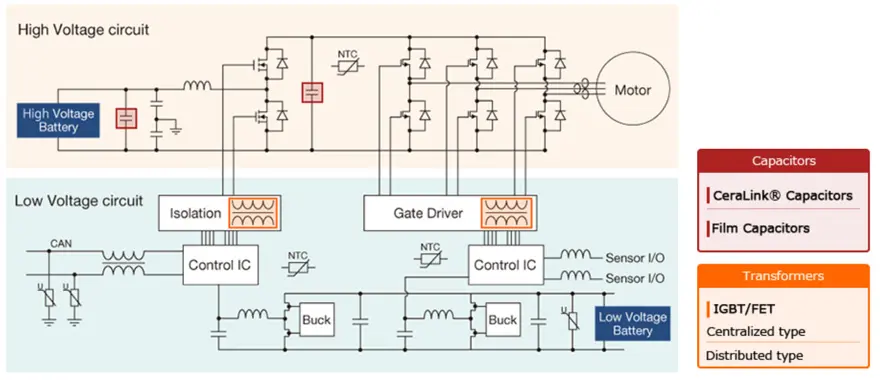
Motor/generator circuit configuration example
Inverter circuits that convert direct current to alternating current are used to drive motors and generators. Such circuits incorporate Insulated-Gate Bipolar Transistors (IGBT) and other semiconductor switches. Recently, Silicon Carbide (SiC) and other high-speed devices are also coming into use, operating at higher frequencies while featuring smaller dimensions. Driving a large electric motor requires voltages of 400 volts and higher. A booster circuit therefore is generally placed in front of the inverter circuit, and a configuration with two semiconductor switches is used to increase efficiency. When the motor is driven, a steep current rise occurs which requires the high-voltage line connecting the booster circuit and the inverter to be stabilized. This task is performed by a capacitor called DC LINK.
Capacitors for DC Link/Snubber Use
The use of high-speed devices such as SiC, Gan etc. is progressing and the dimensions of inverters are shrinking, but this makes it even more important to effectively control noise. Wiring inductance can lead to high surge voltages which requires countermeasures such as suitable wiring design and snubber capacitors.
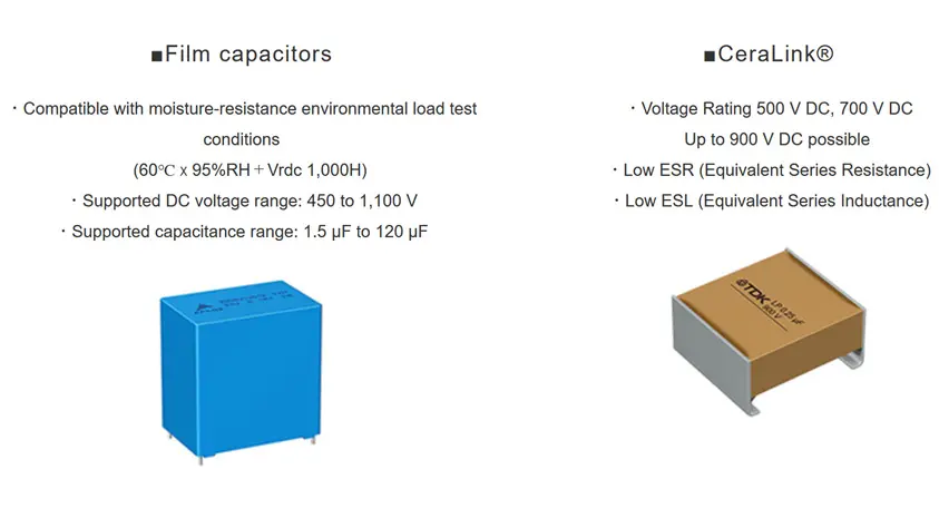
Film Capacitors
Inverter circuit inputs require a stable DC voltage at the input. Because electric motors are driven at low frequencies, a relatively large capacitance is required to absorb ripple components. Film capacitors have high allowable ripple current ratings, making them suitable for achieving stable voltage.
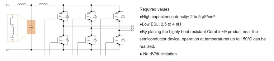
CeraLink® Snubber Circuit Application Example
When an electric motor is driven, a steep current rise occurs. This generates a large ringing voltage which results in noise and can lead to withstand voltage degradation in semiconductor devices. Although CeraLink® are SMD products, they realize high withstand voltage and high capacitance. While harnessing the advantages of the SMD format to optimize the pattern layout, parasitic inductance in the wiring can be kept low. Furthermore, the ESL of the devices themselves is low, which makes it possible to reduce ringing voltage generation.
Transformers for IGBT/FET Drive
Motor drive inverter circuits and high-power converters use a bridge circuit configuration, which consists of semiconductor switches for the high voltage side and the low voltage side. A stable power supply is required for driving these semiconductor switches. The high side in particular has to be able to handle voltages up to 800 V for electric vehicle motors. A power supply that is insulated from the low side is required, and a compact, transformer with high withstand voltage is used for this purpose. Moreover, since multiple semiconductor switches are used and the gate voltage varies, causing reliability differences between devices, voltage equalization is desirable.
Example of IGBT/FET Drive Transformer
IPM (Intelligent Power Modules) are used for high-power inverters, booster circuits, and similar. They are semiconductor components created by combining power devices such as power MOS-FETs or IGBTs with a drive circuit and an integrated self-protection function.
A power supply voltage of 15 V ±10% is required to drive an IPM. Transformers are used to provide insulation from power devices, but poor characteristics of the transformer will degrade voltage stability. The wire material is also crucial in terms of achieving the required insulation reliability. Material that can withstand high temperatures is therefore used. If space and cost are the top considerations, the choice will be an integrated transformer. By contrast, if layout design freedom and voltage stability are given priority, the choice is a distributed transformer.


