Passive Components Blog
No Result
View All Result
  • Home
  • NewsFilter
    • All
    • Aerospace & Defence
    • Antenna
    • Applications
    • Automotive
    • Capacitors
    • Circuit Protection Devices
    • electro-mechanical news
    • Filters
    • Fuses
    • Inductors
    • Industrial
    • Integrated Passives
    • inter-connect news
    • Market & Supply Chain
    • Market Insights
    • Medical
    • Modelling and Simulation
    • New Materials & Supply
    • New Technologies
    • Non-linear Passives
    • Oscillators
    • Passive Sensors News
    • Resistors
    • RF & Microwave
    • Telecommunication
    • Weekly Digest

    DigiKey Offers Zephyr Operating System Workshop and Training Videos

    Exxelia to Present Smart Integrated Magnetics and MML Film Capacitors at SIAE25 

    What Track Width To Use When Routing PCB

    YAGEO Unveils PulseChip LAN Transformer

    Bourns Releases Automotive Impedance Matching Transformer

    Stackpole Offers Affordable Current Sense Chip Resistors

    Knowles Extends Range and Performance of C0G MLCC Capacitors

    May 2025 ECST Component Results Show Moderating Decline in Sales Sentiment

    Panasonic Releases New Aluminum Hybrid Capacitors with High Ripple Current in Compact Size

    Trending Tags

    • Ripple Current
    • RF
    • Leakage Current
    • Tantalum vs Ceramic
    • Snubber
    • Low ESR
    • Feedthrough
    • Derating
    • Dielectric Constant
    • New Products
    • Market Reports
  • VideoFilter
    • All
    • Antenna videos
    • Capacitor videos
    • Circuit Protection Video
    • Filter videos
    • Fuse videos
    • Inductor videos
    • Inter-Connect Video
    • Non-linear passives videos
    • Oscillator videos
    • Passive sensors videos
    • Resistor videos

    Coupled Inductors Circuit Model and Examples of its Applications

    Inductor Resonances and its Impact to EMI

    Highly Reliable Flex Rigid PCBs, Würth Elektronik Webinar

    Causes of Oscillations in Flyback Converters

    How to design a 60W Flyback Transformer

    Modeling and Simulation of Leakage Inductance

    Power Inductor Considerations for AI High Power Computing – Vishay Video

    Coupled Inductors in Multiphase Boost Converters

    VPG Demonstrates Precision Resistor in Cryogenic Conditions

    Trending Tags

    • Capacitors explained
    • Inductors explained
    • Resistors explained
    • Filters explained
    • Application Video Guidelines
    • EMC
    • New Products
    • Ripple Current
    • Simulation
    • Tantalum vs Ceramic
  • Knowledge Blog
  • Suppliers
    • Who is Who
  • Events
No Result
View All Result
Passive Components Blog
No Result
View All Result

Test Explanations: Mechanical Conditioning

14.9.2021
Reading Time: 2 mins read
A A

Mechanical conditioning are intended to assess the mechanical stability of the contact interface under field conditions. As noted previously in this chapter, disturbances of the contact interface can be driven by either thermal or mechanical forces. The thermal forces result indirectly from thermal expansion mismatch stresses, thermal cycling or thermal shock, while the mechanical forces are applied directly, mechanical shock or vibration.

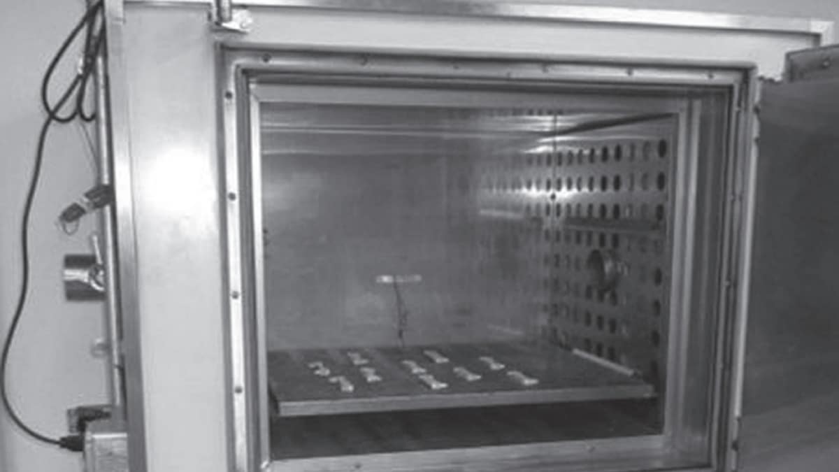
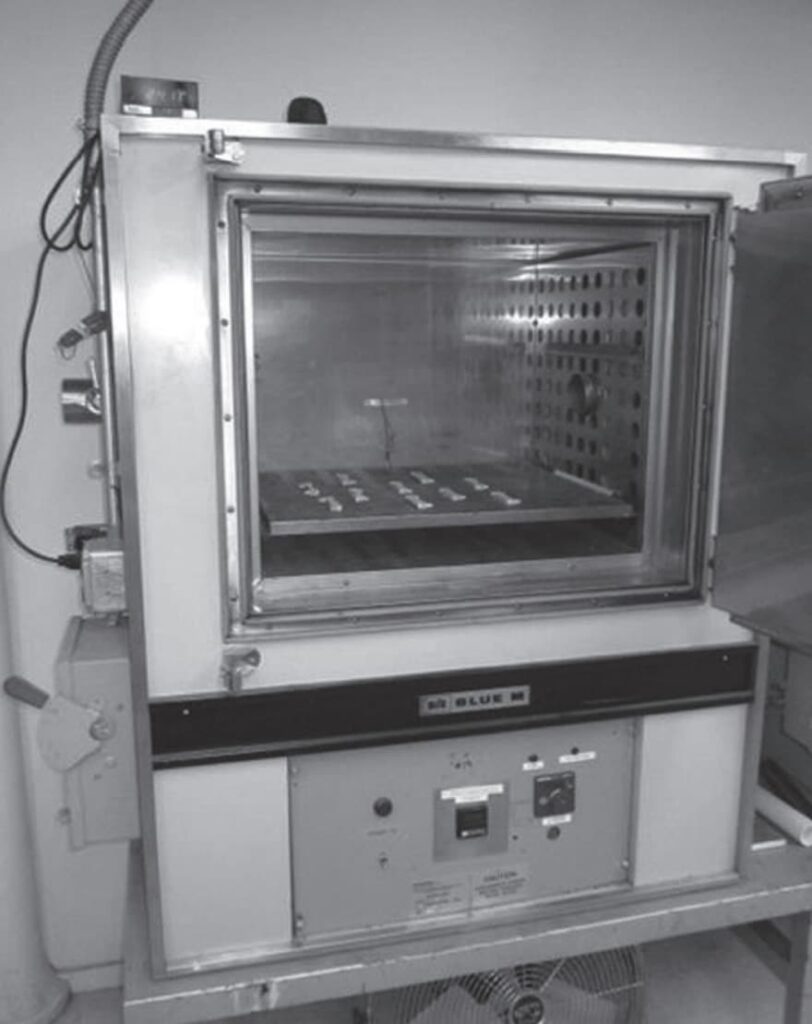
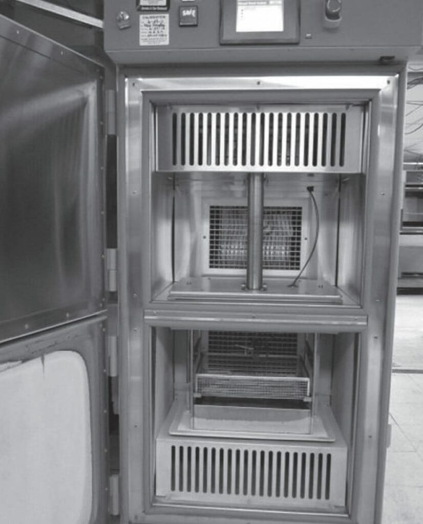
The difference between thermal cycling and thermal shock is the rate of change of temperature between the upper and lower temperature limits. Thermal cycling is generally a slow change in temperature, often by cycling either the applied current or the oven temperature, while thermal shock is generally rapid by moving the samples between chambers at different temperatures. An oven suitable for thermal cycling is shown in Figure 2.116 and a dual chamber, thermal shock oven, in Figure 2.117.

RelatedPosts

Polymer Materials and Processing

What is RF Connector

Connector Materials and Processes

Fig. 2.116: Temperature life, thermal cycling oven
Fig. 2.117 : Dual chamber thermal shock oven

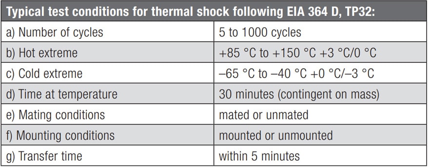
Thermal shock is further differentiated by the different thermal response times of the connector and system components. While the magnitude of the applied stresses may be the same for a given temperature change, the rate of application of the stresses in thermal shock is generally a more demanding environment. The thermal stresses realized are dependent on the size of the connector because the differential change in length is dependent on the length of the connector or system. This fact should be taken into consideration when selecting the samples to be tested. Table 2.7 lists typical conditions of thermal shock.

Tab. 2.7: Typical thermal shock parameters

Mechanical shock is generally intended to simulate transportation stresses, though there are some connector environments, e.g. automotive that experience mechanical shocks as a part of their application environment. The G values and number of shocks applied are application dependent.

Related

Source: Wurth elektronik

Recent Posts

Non-Magnetic Interconnects

23.4.2025
20

10 Tips for Ensuring Reliability of Discrete Wire Assemblies

20.2.2025
51

Polymer Materials and Processing

31.1.2025
36

Basic PCB Technology Overview

17.12.2024
15

What is RF Connector

17.12.2024
7

Creepage and Clearance of Connector

16.10.2023
13

Microwave Multi Line Connectors Mounting and Handling Precautions

17.12.2024
2

BASIC PCB Design Rules – Layout

17.12.2024
23

MEMR RF Relay for Space Compact Redundancy Ring

17.12.2024
2

Connector Temperature Rise and Derating

13.1.2023
15

Upcoming Events

Jun 24
17:00 - 18:00 CEST

Ultra-Compact and Efficient Switched-Capacitor Power Converters

View Calendar

Popular Posts

  • Buck Converter Design and Calculation

    0 shares
    Share 0 Tweet 0
  • Boost Converter Design and Calculation

    0 shares
    Share 0 Tweet 0
  • Flyback Converter Design and Calculation

    0 shares
    Share 0 Tweet 0
  • What is a Dielectric Constant and DF of Plastic Materials?

    4 shares
    Share 4 Tweet 0
  • LLC Resonant Converter Design and Calculation

    0 shares
    Share 0 Tweet 0
  • Ripple Current and its Effects on the Performance of Capacitors

    3 shares
    Share 3 Tweet 0
  • Dual Active Bridge (DAB) Topology Explained

    0 shares
    Share 0 Tweet 0
  • SEPIC Converter Design and Calculation

    0 shares
    Share 0 Tweet 0
  • Flying Capacitors Explained

    0 shares
    Share 0 Tweet 0
  • How to Design an Inductor

    0 shares
    Share 0 Tweet 0

Newsletter Subscription


Passive Components Blog

© EPCI - Leading Passive Components Educational and Information Site

  • Home
  • Privacy Policy
  • EPCI Membership & Advertisement
  • About

No Result
View All Result
  • Home
  • Knowledge Blog
  • Premium Suppliers

© EPCI - Leading Passive Components Educational and Information Site

This website uses cookies. By continuing to use this website you are giving consent to cookies being used. Visit our Privacy and Cookie Policy.
Go to mobile version