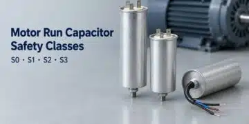


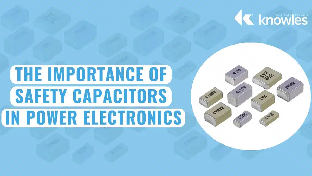
Safety capacitors are certified interference-suppression components used across supply conductors or across insulation boundaries where capacitor failure has safety consequences.
This article explains Class X and Class Y applications, ceramic and film technologies, qualification, and practical selection checks for engineers designing power supplies, mains filters and related power-electronic equipment.
Key Takeaways
- Class X capacitors normally suppress differential-mode noise between supply conductors; Class Y capacitors provide controlled high-frequency coupling to earth or across an insulation boundary.
- Safety class, continuous voltage rating, impulse qualification and equipment insulation requirements are separate selection criteria. An ordinary high-voltage capacitor is not a substitute for an appropriately certified safety capacitor.
- Metallized film is widely used where relatively large across-line capacitance is required. Ceramic disc and multilayer ceramic capacitors provide additional options, including compact line-bypass and isolation-barrier applications.
- Y-capacitor selection must balance common-mode attenuation against touch-current and protective-conductor-current requirements. A Y capacitor does not replace protective earthing.
- Check humidity performance, effective capacitance, temperature, PCB insulation distances, assembly stress and exact approval coverage. Component certification does not certify the finished equipment.
The Role of Safety Capacitors
Safety capacitors are also called EMI/RFI suppression capacitors. Their principal circuit function is to provide a suitable impedance path for high-frequency interference while meeting safety requirements appropriate to their connection point. The X and Y designations concern safety applications, not a particular dielectric material. [1, 2]
Electromagnetic interference, or EMI, can originate in switching converters, motors, relays and other equipment, or arrive through the supply network. A power-line filter limits conducted noise leaving equipment and can also attenuate incoming disturbances. Its performance depends on the noise mode, source and load impedances, layout and the frequency-dependent behavior of its components. [2, 3]
A capacitor combined with series inductance or resistance can form part of a low-pass network. In a power input filter, this network passes the intended supply while attenuating higher-frequency noise. The capacitor is a shunt element: the equipment load current does not normally flow through it. At sufficiently high frequencies, parasitic inductance limits the capacitor’s effectiveness, so nominal capacitance alone does not describe filter performance. [3, 4]
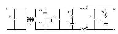
- A common-mode network commonly combines a common-mode choke with Y capacitors connected to an appropriate earth, chassis or isolated reference.
- A differential-mode network commonly combines an X capacitor between supply conductors with differential-mode inductance. The required inductance may come from separate components or from the leakage inductance of a common-mode choke.
- Damping networks may be needed to control resonances and interaction with the converter input impedance; they are not mandatory components of every filter.
- Surge-protection components may be required separately. An X or Y safety classification does not specify a voltage-clamping characteristic.
Figure 1 illustrates an input-filter arrangement. A similar topology can be used on an appropriate DC input, but the selected components must have suitable DC ratings, approvals and insulation coordination. An AC safety rating must not be converted into a DC rating by assumption. [1, 2]
Where Safety Capacitors Are Used
Safety capacitors are used where interference suppression and electrical safety requirements intersect. Typical applications include AC-DC power supplies, appliances, industrial motor drives, HVAC equipment, telecommunications power systems and vehicle charging equipment. Their necessity and classification depend on the actual circuit connection rather than the product category alone. [2, 3]
Not every capacitor in mains-powered equipment needs an X or Y approval. DC-link, resonant, snubber and low-voltage decoupling capacitors have different duties; a high voltage rating or self-healing construction does not by itself qualify them for direct connection across the mains or across safety insulation. Conversely, a safety approval does not establish suitability for a converter’s repetitive ripple-current or pulse duty. [4]
In isolated converters, a safety capacitor may connect the primary and secondary references to control common-mode noise. This connection is not necessarily a connection to protective earth. The required capacitor class must follow the insulation barrier and end-equipment safety requirements. Medical, industrial, consumer and automotive systems can impose different current, insulation and qualification constraints.
Classes of Safety Capacitors
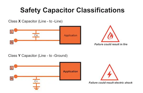
Class X and Class Y describe different safety-related connection duties. Both can be used in EMI filters, but they are not interchangeable merely because capacitance and operating voltage appear similar. Figure 2 shows the conventional mains-filter locations. [2, 5]
Class X: Across the Supply Conductors
Class X capacitors are used where capacitor failure would not directly create an electric-shock hazard, typically between line and neutral or between phases. They provide a high-frequency path for differential-mode noise. A short-circuit failure can create an overcurrent or fire hazard, so suitable fault protection and safe end-of-life behavior remain important. A fuse may clear a fault, but fuse operation is not the definition of an X capacitor and is not guaranteed for every failure mechanism. [4, 5]
Class Y: Across Safety-Relevant Insulation
Class Y capacitors are used where a short-circuit failure could create an electric-shock hazard. Typical positions include line-to-protective-earth connections and coupling across an isolated power supply’s primary-to-secondary boundary. Their electrical and mechanical reliability requirements reflect that consequence. A Y capacitor provides a controlled capacitive path; it does not provide protective earthing or make an otherwise unsafe insulation system acceptable. [2, 4, 5]
Y capacitors conduct displacement current under AC voltage even when their dielectric insulation is intact. Capacitance must therefore be limited by the equipment’s permitted touch current or protective-conductor current, including relevant normal and fault conditions. Approval does not justify assuming that a capacitor can never fail short. [4, 5]
Combined X/Y Markings
A component marked X1/Y2 is approved for an X1 application and a Y2 application under its stated ratings. These are alternative permitted duties of one component, not a combined circuit function. The permissible continuous voltage may differ between the X and Y approvals, so check both the datasheet and the certificate for the exact ordering code. [2]
Safety Capacitor Subclasses
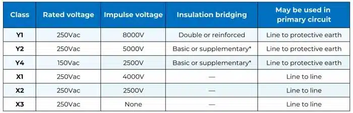
Subclasses distinguish impulse exposure and insulation duty. In the conventional classification summarized in manufacturer guidance, X1 covers operating peak impulses above 2.5 kV and up to 4 kV, X2 up to 2.5 kV, and X3 up to 1.2 kV. These figures are not continuous working voltages or voltage-clamping levels. Qualification test details can also depend on capacitance and the applicable specification. [5]
Y1 is associated with bridging double or reinforced insulation, while Y2 is associated with basic or supplementary insulation. Conventional manufacturer guidance identifies impulse test levels of 8 kV for Y1 and 5 kV for Y2. Y3 and Y4 have distinct requirements and must not be treated simply as options for less important equipment. In particular, Y1 does not mean that the capacitor must operate above 500 V AC. [2, 5]
Table 1 retains the article’s original graphical subclass overview. Use the current standard and the selected component’s approval documents for final selection: historical overview tables are not substitutes for the actual approved voltage range, insulation duty or test conditions. [1]
Do not infer that placing two lower-class capacitors in series automatically establishes a higher insulation classification. Any permitted series arrangement must be evaluated against the equipment standard, the required fault assumptions, individual component approvals and PCB insulation distances.
Mains Transients and Safe Connection
Supply disturbances can originate outside the equipment or from switching within it. Their severity depends on installation conditions, overvoltage category and the equipment’s protective network. Select capacitor impulse capability as part of that system assessment rather than from a universal assumption about the number or duration of daily transients. IEC 60384-14 relates overvoltage categories and mains voltages to IEC 60664-1. [1]
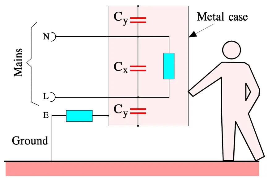
Figure 3 shows the conventional connection of X and Y capacitors. X capacitors attenuate differential-mode interference; Y capacitors provide common-mode current paths. Neither function eliminates the need for surge coordination, appropriate fault protection or a correctly designed protective-earth connection. [2, 5]
Qualification and Current Standards
IEC 60384-14:2023+AMD1:2025, edition 5.1, is the current consolidated IEC publication at this review. Its scope includes capacitors and resistor-capacitor combinations for supplies up to 1000 V AC RMS at frequencies up to 100 Hz, with additional conditions for DC supplies up to 1500 V DC. Those are standard-scope limits, not ratings assigned to every certified capacitor. [1]
The published changes include damp-heat testing with and without rated voltage, a normative annex addressing capacitor styles and creepage/clearance measurement, and increased emphasis on mechanical cracks in encapsulation. Qualification covers more than endurance and impulse survival: relevant electrical, environmental, mechanical and safety tests must be considered together. [1]
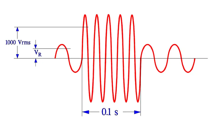
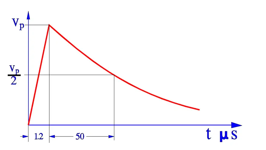
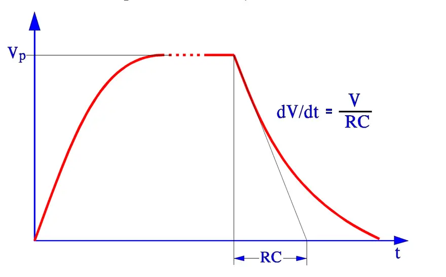
Figures 4 to 6 retain the article’s historical endurance, surge and charge/discharge illustrations. They explain categories of stress, not a complete current qualification procedure. Apply the test voltage, waveform, duration, repetition and acceptance limits specified for the selected class, construction and standard edition. Do not reuse a historical diagram as a production test instruction. [1, 5]
For procurement, verify the applicable regional approvals and their conditions rather than requiring an unspecified national mark for every country. The approved component must match the actual class, voltage, capacitance, construction and ordering-code range. A component approved to an earlier edition is not automatically unsuitable, but its acceptance must be checked against the equipment’s certification requirements.
Incoming inspection and equipment dielectric testing are not opportunities to repeat component qualification stresses arbitrarily. Repeated high-voltage testing can damage capacitors; agree the equipment test method and any treatment of installed safety capacitors with the manufacturer and certification body. [5]
General Considerations for Selecting a Safety Capacitor Technology
Select the safety duty before selecting the dielectric. Film, ceramic disc and multilayer ceramic technologies overlap in application, but differ in available capacitance, package, dielectric behavior, assembly process and qualification coverage. The approved part, rather than the material name, determines suitability. [2]
Compare the continuous AC and DC ratings, impulse capability, capacitance tolerance, operating temperature, humidity qualification, frequency-dependent losses and package dimensions. Include assembly cost and lifetime performance, not only the component price. For ceramic parts, distinguish the dielectric’s Class 1 or Class 2 designation from the unrelated X/Y safety classification.
Package geometry influences insulation distances but does not establish compliance of the complete PCB. Evaluate creepage along surfaces and clearance through air around pads, tracks, vias, slots, mounting hardware and adjacent components. Lead spacing alone is not a substitute for insulation coordination, and changing to an SMD package does not remove the safety boundary. [1]
Ceramic Capacitors
Ceramic safety capacitors include single-layer disc capacitors as well as MLCCs. Disc constructions are established options for high dielectric strength and impulse capability, including Y1 duties. MLCCs can offer compact surface-mount assembly and useful high-frequency behavior. It is therefore incorrect to treat all ceramic safety capacitors as MLCCs or as inherently lower-voltage alternatives to film. [2]
- Certified ceramic parts are available for selected X and Y duties; verify the class and rating of the exact series and value.
- Surface-mount construction can simplify automated assembly, but the safety-capacitor footprint may be larger than an ordinary MLCC footprint because insulation distances remain important.
- Short connections can reduce equivalent series inductance, or ESL. Actual high-frequency attenuation still depends on placement, loop geometry and the complete filter.
- Ceramic dielectric choice affects usable capacitance. Stable dielectrics and higher-permittivity dielectrics must not be compared on nominal capacitance alone.
For an MLCC using a Class 2 dielectric, account for capacitance change with applied voltage, temperature and aging using the manufacturer’s data. Check the remaining capacitance at the actual operating point, including any DC bias or superimposed AC voltage. A dielectric code is not a guarantee of constant capacitance under every operating condition.
Mechanical integrity is equally important. PCB bending, depanelization, assembly forces and thermal stress can crack ceramic components or their encapsulation. Safety approval does not remove the need to follow mounting and soldering instructions. Current IEC guidance explicitly emphasizes mechanical cracking as a safety-related concern. [1]
Surface mounting is not synonymous with multilayer construction. Surface-mount ceramic disc safety capacitors provide another packaging option; designers must still assess the internal construction, approved insulation duty, soldering profile and board-level distances independently.
Film Capacitors
Metallized film capacitors are widely used in across-line filters, especially where relatively large capacitance is required. Their self-healing construction can isolate localized dielectric defects by clearing a small area of metallization. This behavior belongs to the construction; it must not be attributed indiscriminately to every film/foil capacitor. [2, 4]
- Available capacitance makes metallized film practical for many differential-mode mains-filter positions.
- Self-healing can restore insulation after a localized breakdown, with some loss of active electrode area and capacitance.
- Suitable film constructions offer low losses and useful capacitance stability, subject to the selected dielectric, operating temperature and electrical stress.
- Certified film capacitors are also available for Y duties; film is not restricted to Class X applications. [2, 4]
Film parts can occupy more board volume than small-value ceramic alternatives and may require a different assembly process. However, size and price must be compared at the required capacitance, rating and qualification level, not as universal material properties.
Humidity performance deserves explicit attention. Moisture-related degradation of metallization or terminations can reduce capacitance even while the capacitor remains apparently functional. Compare the manufacturer’s declared damp-heat test conditions and permitted parameter changes; neither the word film nor a self-healing claim guarantees suitability for a humid installation. [2, 5]
Ceramic vs. Film Safety Capacitors in Practice
A useful starting point is metallized film for larger across-line capacitance and ceramic for many small-value line-bypass or isolation-coupling positions. This is a practical tendency, not a rule assigning X to film and Y to ceramic. Ceramic X capacitors and film Y capacitors are established alternatives. [2]
Filter performance should be compared at the operating frequency and voltage. A compact capacitor with favorable ESL may improve a high-frequency path, while a larger-capacitance film part may be more appropriate for a different part of the differential-mode spectrum. A safety-class change should follow impulse and insulation requirements, not an assumption that higher converter power automatically requires X1 or Y1.
| Aspect | Ceramic safety capacitors | Metallized film safety capacitors |
|---|---|---|
| Construction | Single-layer disc or multilayer ceramic; leaded or surface-mount options | Metallized dielectric or carrier-film constructions with approved encapsulation |
| Typical selection reason | Small-value filtering, compact assembly, high dielectric strength or suitable high-frequency impedance | Larger across-line capacitance, low losses and self-healing behavior |
| Safety duty | Selected X and Y approvals, depending on the series | Selected X and Y approvals, depending on the series |
| Main design checks | Effective capacitance, dielectric behavior, mechanical damage, insulation distances and soldering | Capacitance retention, humidity qualification, temperature, pulse duty and package volume |
| Cost comparison | Compare the exact approved part and assembly process | Compare the exact approved part and assembly process |
Example: Safety Capacitors in an AC-DC Power Supply
Consider an earthed, Class I offline AC-DC power supply. An appropriately rated X2 metallized film capacitor can be placed between line and neutral for differential-mode attenuation. Appropriately rated Y capacitors can connect line and neutral to protective earth for common-mode filtering. A common-mode choke and any required differential-mode inductance complete the relevant filter paths. [2, 5]
The X capacitor must withstand its specified operating and transient environment; it is not a replacement for a surge clamp. The Y-capacitor values must satisfy the equipment’s current limits, and the protective-earth connection must meet its own safety requirements. Insulation distances must be maintained around the complete filter assembly.
A Class II charger without protective earth requires a different treatment. Its common-mode coupling capacitor may bridge primary-to-secondary safety insulation rather than connect to earth. Do not copy the Class I arrangement or choose Y2 solely because the product is compact. Select the approved arrangement for the insulation barrier, including reinforced-insulation requirements where applicable.
Likewise, industrial equipment does not automatically need a change from X2 to X1 or from Y2 to Y1 because its output power is higher. Determine supply voltage, overvoltage exposure, insulation duty, environmental stress and the end-equipment standard first. These requirements then define the candidate parts and protection network.
MP or MK Film Capacitors?
MP denotes metallized paper, while MK denotes metallized plastic-film construction. Common plastic-film designations include MKT for metallized polyester and MKP for metallized polypropylene. These construction terms help explain behavior, but none is itself an X or Y approval. [4, 6]
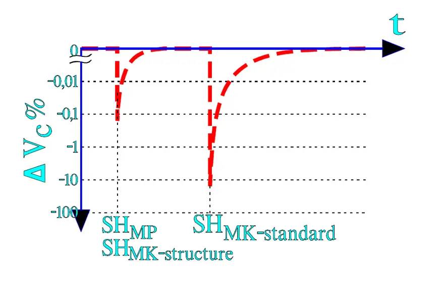
During self-healing, localized electrical breakdown generates heat that removes metallization around a defect, isolating the conductive path. The clearing energy and disturbance to capacitor voltage depend on electrode material, metallization thickness, dielectric, winding construction and the surrounding circuit. A generic ranking based only on zinc versus aluminum metallization is therefore insufficient for selection. [4, 6]
Figure 7 retains the original qualitative comparison of voltage disturbance during self-healing. It illustrates a construction-dependent effect, not a guaranteed performance ordering for all modern MP and MK capacitors. Use manufacturer data for repetitive stress, capacitance loss and end-of-life behavior.
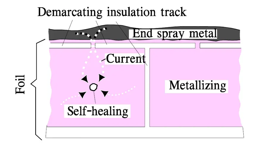
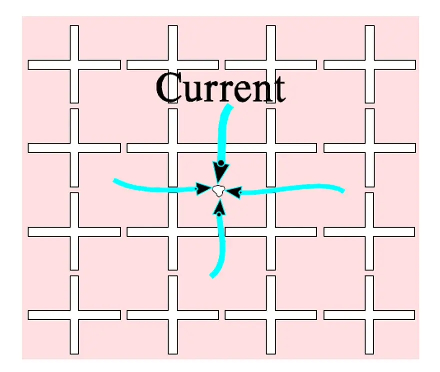
Segmented metallization divides an electrode into regions connected through narrow conductive links. A fault can clear a link and disconnect an affected region, limiting the energy supplied by neighboring regions. Figures 8 and 9 illustrate this principle. Segmentation and local self-healing are related protective mechanisms, but they are not identical events. [4]
Polypropylene offers low dielectric losses and is widely used in AC and pulse applications. However, its dielectric properties do not make segmentation unnecessary in every design. The electrode pattern, metallization and winding must be selected for the intended electrical duty and failure behavior. [4]
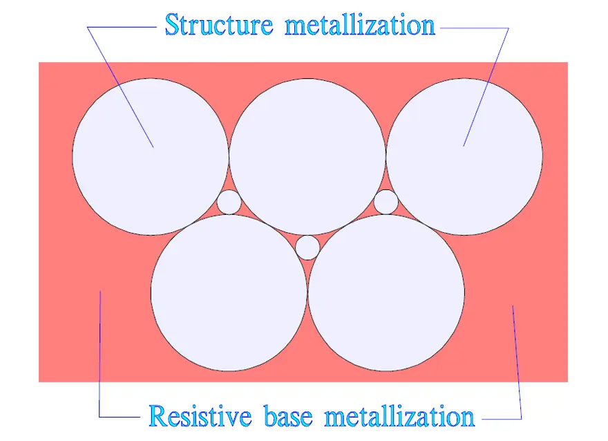
Another historical structure uses circular metallized regions and weaker connecting areas, as illustrated in Figure 10. Such patterns show how electrode geometry can control fault energy. Their presence does not independently establish a safety class, humidity capability or lifetime rating.
Clearing removes active electrode area, and repeated events can reduce capacitance. A capacitor can consequently lose EMI-filter effectiveness without developing a permanent short circuit. Compare capacitance retention, dissipation factor and insulation resistance after the specified endurance and environmental tests. Do not select MP or MK solely from a historical claim that one is universally superior. [4, 6]
Selecting the Right Safety Capacitor for Your Design
Selection starts with circuit position and ends with validation of the finished equipment. The following checks connect safety classification, filtering performance, assembly and purchasing requirements so that a nominally equivalent replacement does not silently change the design.
Budget Y-Capacitor Current
For a capacitor under sinusoidal voltage, Eq. (1) gives the ideal RMS displacement current. IC is current in amperes, f is frequency in hertz, C is capacitance in farads, and Vrms is the RMS voltage across that capacitor in volts. This current is different from DC leakage through the dielectric.
Use Eq. (1) for an initial power-frequency budget, with maximum relevant voltage, frequency and capacitance. The complete equipment assessment must also account for other capacitive paths, switching-frequency components, supply arrangements, normal and fault conditions, and the prescribed measurement network. Do not simply add nominal line-to-earth capacitances and treat the result as a universal touch-current calculation. Y-capacitor capacitance is limited for safety reasons, but there is no single maximum value applicable to every product. [4, 5]
Check Stored Charge and Discharge Paths
An across-line capacitor can retain charge after the supply is disconnected. Where the equipment requirements call for discharge, provide a suitable resistor or approved active discharge arrangement and evaluate its failure behavior. For an ideal isolated capacitor C discharged only through resistance R, Eq. (2) gives the time t to fall from initial voltage V0 to a lower positive voltage Vsafe.
In Eq. (2), t is in seconds, R in ohms and C in farads; both voltages use the same unit. Use worst-case component tolerances and the actual initial voltage. The permitted residual voltage and discharge time come from the applicable equipment requirements, not from the X2 marking. Check resistor voltage stress, continuous dissipation and any additional circuit paths. The equation is the ideal RC discharge relationship. [7]
Design and Selection Checklist
- Define the connection: line-to-line, line-to-neutral, line-to-earth or across an insulation barrier. Identify the required X or Y subclass and insulation duty.
- Check the exact approved continuous AC and DC ratings, frequency range, impulse qualification and temperature derating. Do not use a test voltage as a working voltage.
- Compare nominal and effective capacitance, tolerance, temperature dependence, voltage dependence, aging and expected capacitance retention.
- Check impedance, ESR and ESL over the noise-frequency range. Include terminal and PCB-path inductance rather than relying on an ideal capacitor model.
- Check repetitive voltage, current, pulse slope and self-heating. A safety impulse test is not a repetitive operating rating.
- For Y positions, document the touch-current or protective-conductor-current budget and the required normal and fault-condition measurements.
- For across-line positions, assess retained charge, any discharge network, fault protection and coordination with surge-protection components.
- Compare humidity qualification, climatic category, encapsulation integrity and permissible parameter drift under the intended environment.
- Verify creepage, clearance and insulation coordination on the complete assembly, including contamination, altitude and mechanical hardware where relevant.
- Review soldering, cleaning, rework, PCB flex and depanelization limits. Inspect for damage that could compromise encapsulation or ceramic integrity.
- For purchasing, record the exact manufacturer and ordering code, certificate coverage, approved values, package and lead form, traceability and change-notification requirements.
- For catalog alternatives, compare approval documents as well as electrical dimensions. For custom parts or changed lead geometry, obtain written confirmation of approval coverage; customization does not automatically inherit the original certificate.
- Where automotive qualification is required, verify it separately from safety certification. AEC-Q200 qualification and an X/Y approval address different requirements. [2]
- Validate the final filter for conducted emissions, relevant immunity tests, current limits, thermal behavior and equipment safety with representative wiring and operating modes.
Conclusion
Safety-capacitor selection is an insulation and qualification decision as well as an EMI-filter decision. Select the connection duty and required approval first, then choose capacitance, dielectric and package for the real operating conditions.
Metallized film, ceramic disc and MLCC constructions all have useful roles. None removes the need to check continuous ratings, impulse exposure, current limits, humidity, mechanical integrity and board-level insulation. The final evidence is the combination of the exact component documentation and successful assessment of the finished equipment.
FAQ
These answers summarize the selection principles above. Final component acceptance depends on the actual circuit and equipment requirements.
Class X capacitors are used where failure would not directly create an electric-shock hazard, typically between supply conductors. Class Y capacitors are used where failure could compromise protection against electric shock, including line-to-earth and isolation-barrier connections. Select the subclass, voltage rating and approved construction for the actual circuit position rather than from capacitance alone.
A high voltage rating alone does not establish suitability for a safety-capacitor position. The replacement must have the required X or Y approval, continuous rating, insulation duty and environmental capability. Check the exact ordering code and certificate coverage. A self-healing film construction or automotive qualification does not independently replace the required safety approval.
Choose the safety duty first, then compare approved parts. Metallized film is widely used for larger across-line capacitance, while ceramic disc and multilayer constructions serve many small-value filtering and isolation-coupling duties. Compare effective capacitance, impedance, voltage, humidity qualification, mechanical integrity and assembly cost. Neither ceramic nor film is restricted to one safety class.
Y capacitors conduct displacement current whenever AC voltage appears across them, even with intact insulation. Increasing capacitance can improve common-mode filtering but increases this current. Calculate an initial power-frequency budget, then assess the complete equipment using the required measurement method and fault conditions. Protective-conductor current, touch current and DC dielectric leakage are different quantities.
An X capacitor provides a high-frequency path for differential-mode interference and must withstand its specified electrical environment. Its safety class does not define a voltage-clamping characteristic or guarantee protection of downstream components. Evaluate surge protection, fault protection and capacitor stress together. A qualification impulse test also does not establish an unlimited repetitive pulse rating.
IEC 60384-14 covers interference-suppression capacitors and related resistor-capacitor combinations within its stated supply limits. The consolidated publication at this review is IEC 60384-14:2023+AMD1:2025. Check the applicable regional approvals, certificate conditions and equipment requirements as well. Component certification does not certify PCB insulation distances, touch current or the finished product.
How to Select and Validate a Safety Capacitor
Use this procedure during initial design and whenever an approved component is replaced. Retain the supporting calculations and approval documents in the design record.
Select and validate a safety capacitor for a defined power-electronic application.
- Define the connection and insulation duty
Identify whether the capacitor connects supply conductors, connects to protective earth or bridges an insulation barrier. Establish the required safety subclass and equipment requirements before choosing a dielectric.
- Establish electrical limits
Document maximum continuous voltage, supply frequency, impulse exposure, repetitive pulse stress and temperature. Set the Y-capacitor current budget and any across-line discharge requirement.
- Compare approved candidate parts
Compare film, ceramic disc and multilayer ceramic candidates using effective capacitance, impedance, humidity qualification, package, soldering limits and exact certificate coverage. Confirm custom variations and proposed alternatives in writing.
- Check layout and assembly
Verify creepage and clearance throughout the assembly. Review grounding, current-loop geometry, PCB bending, depanelization, cleaning, reflow and rework conditions against the component instructions.
- Validate and release the complete equipment
Test representative operating modes for emissions, relevant immunity, current limits and temperature. Complete the equipment safety assessment and retain the exact ordering codes, certificates, test evidence and substitution rules.
Further Reading
These related articles provide background on capacitor construction and application-specific filtering.
- MLCC and Ceramic Capacitors: construction, dielectric behavior and mechanical considerations behind ceramic selection.
- Capacitor, What Is It?: capacitance, energy storage and the distinction between capacitor circuit functions.
- Filter Capacitors in Electric Vehicles: context for battery-system filtering and isolated DC/DC coupling.
- Surface-Mount Y1 Ceramic Disc Safety Capacitors: a packaging example that distinguishes surface mounting from multilayer construction.
References
The references support the principles and standard information cited above. For production release, use the applicable standard edition and the latest documentation for the selected component.
- International Electrotechnical Commission, IEC 60384-14:2023+AMD1:2025 CSV: Fixed Capacitors for Electromagnetic Interference Suppression and Connection to the Supply Mains, IEC, 2025.
- Martin Leupold, Helder Carneiro and Markus Rößler, Vishay Safety Capacitors: Film, Ceramic Single Disc, and MLCC Technologies and Key Features, Vishay Intertechnology, application note 45023, 2020.
- Jordan Yates, What Are EMI Filters?, Knowles Precision Devices, 2023.
- Vishay Roederstein, Film Capacitors: General Technical Information, Vishay Intertechnology, document 26033, 2022.
- EPCOS AG, EMI Suppression Capacitors: General and Standards, TDK Group, 2018.
- Passive Components Blog, Film and Foil Organic Dielectric Capacitors, Passive Components Blog, updated 2026.
- Passive Components Blog, Capacitor, What Is It?, Passive Components Blog, updated 2026; linked in Further Reading.
Technical review and revision: 3 November 2026. Updated safety-class explanations, standards coverage, technology comparisons and design-selection guidance