Passive Components Blog
No Result
View All Result
  • Home
  • NewsFilter
    • All
    • Aerospace & Defence
    • Antenna
    • Applications
    • Automotive
    • Capacitors
    • Circuit Protection Devices
    • electro-mechanical news
    • Filters
    • Fuses
    • Inductors
    • Industrial
    • Integrated Passives
    • inter-connect news
    • Market & Supply Chain
    • Market Insights
    • Medical
    • Modelling and Simulation
    • New Materials & Supply
    • New Technologies
    • Non-linear Passives
    • Oscillators
    • Passive Sensors News
    • Resistors
    • RF & Microwave
    • Telecommunication
    • Weekly Digest

    Inductor Resonances and its Impact to EMI

    Developing Low Inductance Film Capacitor using Bode 100 Analyzer

    Highly Reliable Flex Rigid PCBs, Würth Elektronik Webinar

    Würth Elektronik Releases High Performance TLVR Coupled Inductors

    YAGEO Extends Rectangular Aluminum Electrolytic Capacitor Family

    Dr. Tomas Zednicek Vision for Europe 2025 Passive Electronics Market

    Littelfuse Releases Industry-First SMD Fuse with 1500A Interrupting Rating at 277V

    TDK Unveils Industry Highest Rated Current Multilayer Chip Beads

    Vishay Releases Automotive SMD Thick Film Power Resistor for Enhanced Protection Against Short Transient Pulses

    Trending Tags

    • Ripple Current
    • RF
    • Leakage Current
    • Tantalum vs Ceramic
    • Snubber
    • Low ESR
    • Feedthrough
    • Derating
    • Dielectric Constant
    • New Products
    • Market Reports
  • VideoFilter
    • All
    • Antenna videos
    • Capacitor videos
    • Circuit Protection Video
    • Filter videos
    • Fuse videos
    • Inductor videos
    • Inter-Connect Video
    • Non-linear passives videos
    • Oscillator videos
    • Passive sensors videos
    • Resistor videos

    Inductor Resonances and its Impact to EMI

    Highly Reliable Flex Rigid PCBs, Würth Elektronik Webinar

    Causes of Oscillations in Flyback Converters

    How to design a 60W Flyback Transformer

    Modeling and Simulation of Leakage Inductance

    Power Inductor Considerations for AI High Power Computing – Vishay Video

    Coupled Inductors in Multiphase Boost Converters

    VPG Demonstrates Precision Resistor in Cryogenic Conditions

    Comparison Testing of Chip Resistor Technologies Under High Vibration

    Trending Tags

    • Capacitors explained
    • Inductors explained
    • Resistors explained
    • Filters explained
    • Application Video Guidelines
    • EMC
    • New Products
    • Ripple Current
    • Simulation
    • Tantalum vs Ceramic
  • Knowledge Blog
  • Suppliers
    • Who is Who
  • Events
No Result
View All Result
Passive Components Blog
No Result
View All Result

Using Resistors for Current Sensing: It’s More Than Just I = V/R

24.8.2022
Reading Time: 8 mins read
A A

Bill Schweber | Mar 29, 2018. Sensing current by measuring voltage across a resistor is simple and elegant, but issues arise with the electrical interface, sizing and selection, and thermal/mechanical considerations.

Measuring dynamic current flow has always been an important parameter for managing system performance, and doing so has become even more so with the proliferation of smarter management functions for devices and systems. The most-common way to accurately make this measurement is by using a sense resistor of known value inserted in series with the load, then measuring the IR voltage drop across this resistor. By applying Ohm’s law, determination of the current flow is simple—or at least that’s how it seems.

RelatedPosts

Inductor Resonances and its Impact to EMI

Developing Low Inductance Film Capacitor using Bode 100 Analyzer

Highly Reliable Flex Rigid PCBs, Würth Elektronik Webinar

While using a resistor is an effective and direct basis for such sensing, it also has many design issues and subtleties despite its clarity. These span the electrical interface, resistor sizing and selection, and many mechanical considerations:

The Electrical Interface

Do you go with high-side or low-side sensing? In low-side sensing, the resistor is placed between the load and “ground” (or, in many cases, circuit “common”) (Fig. 1), which enables the voltage-sensing circuit to also be connected directly to ground. While components in this topology aren’t subject to any high-voltage issues, it’s often undesirable and even unacceptable, for two reasons.

1. Low-side sensing places the resistor between the load and common; it simplifies the interface to the voltage-reading analog front end but brings problems with load integrity and control.
2. High-side sensing is the more commonly used approach, despite the fact that it brings new issues of common-mode voltage.

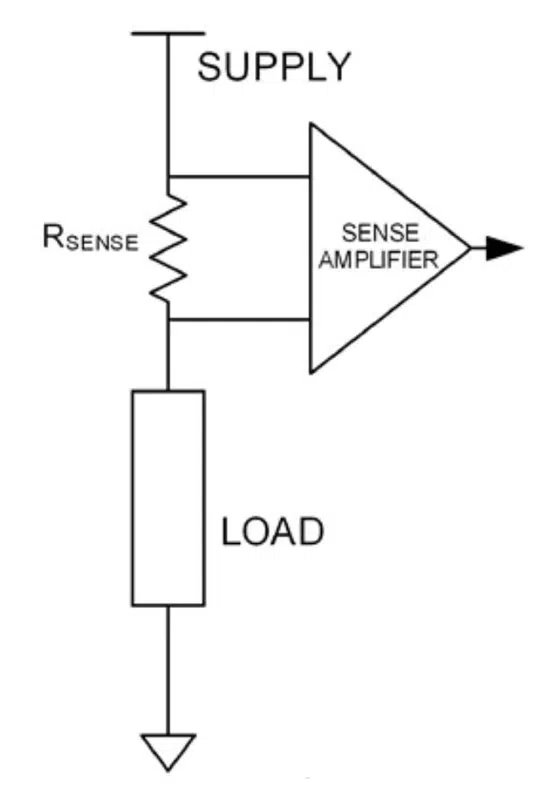
First, doing so means the load itself isn’t grounded, which is impractical for mechanical reasons in many installations. For example, having an ungrounded starter motor in a car and insulating it from the chassis is a design and mounting challenge. It also mandates the need for a return wire that can carry the load current back to the source, rather than using the chassis. Second, even if wiring and mounting aren’t considerations, placing any resistance between the load and ground (common) negatively affects the control-loop dynamics and control.

The solution is to use high-side sensing, with the resistor instead placed between the power rail and the load (Fig. 2). This eliminates the problems created by ungrounding the load, but a new issue arises. The circuitry that senses the voltage across that resistor now can’t be grounded, which means a differential or instrumentation amplifier is used. This amplifier must have a common-mode voltage (CMV) rating that’s higher than the rail voltage. In general, if the rail voltage is higher than the CMV rating of standard ICs (typically, about 100 V), then more complicated approaches to providing this interface are needed.

3. Galvanic isolation can be achieved in several ways. Regardless of approach used, the result is signal information is passed across a barrier without any ohmic path between input and output.

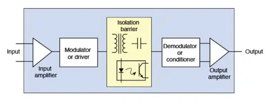
An alternate approach is to use interface circuitry that includes galvanic isolation between the sensing amplifier input and output (Fig. 3). This means no ohmic path exists between the two analog sections—it appears like a non-isolated amplifier, except for the internal isolation.

The approach brings other beneficial features as well: It greatly improves system performance by eliminating ground loops and associated issues; simplifies subsequent circuitry, and eases or eliminates safety-related layout and wiring requirements on clearance and creepage; adds an electrical safety barrier between the high voltage and the rest of the system; and is mandated by safety and regulatory standards in many applications.

4. Isolation is sometimes implemented in the digital domain using an isolated front end (amplifier, ADC, isolator) and an isolated power supply. This AD7401A places all of the needed functions in a single package. (Courtesy of Analog Devices Inc.)

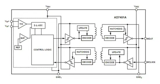
Isolation can be implemented using an all-analog isolation amplifier; alternatively, a subcircuit comprised of a non-isolated amplifier followed by an analog-to-digital converter and isolator (which may use optical, capacitive, magnetic principles), all operating from an isolated power supply that’s independent of the main supply, can be used (Fig. 4). Regardless of the isolation solution selected, the voltage-sensing circuit for higher rail voltages can become complicated with respect to BOM and layout, but there often is no other practical option.

Resistor Sizing and Selection

Ideally, the sensing resistor value should be relatively large so that the resultant voltage drop will also be large, thus minimizing effects of circuit and system noise on the sensed voltage, as well as maximizing its dynamic range. However, a larger value at a given current also means there is less voltage—and thus less available power—for the load due to IR drop, as well as I2R resistor self-heating, wasted power, and added thermal load. It’s clearly a tradeoff and compromise situation.

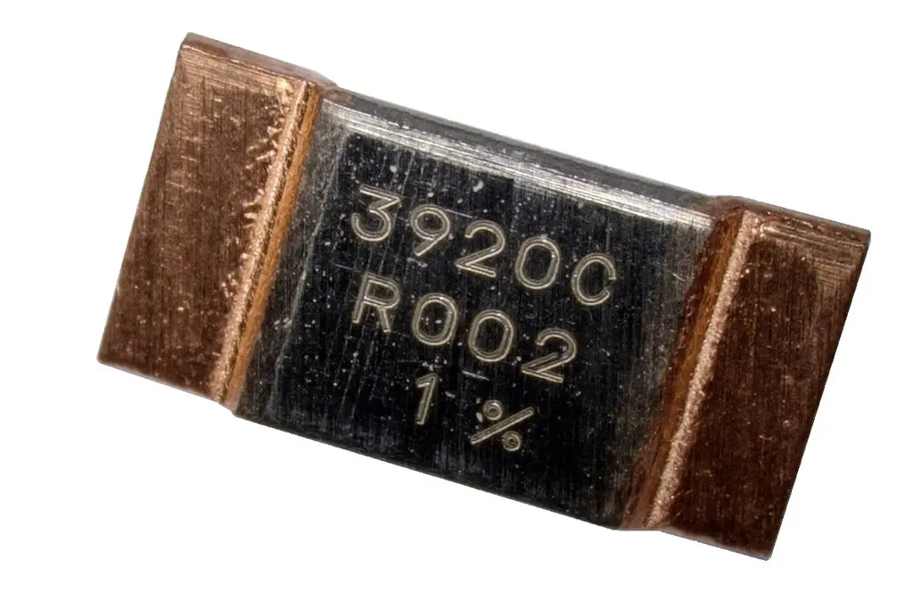
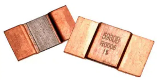
In practice, it’s generally desirable to keep the maximum voltage across the sensing resistor to 100 mV or below, so that the corresponding resistor values are in the tens-of-milliohms range and even lower. Sense resistors are widely available in these small values; even 1-mΩ and lower resistors are standard catalog offerings (Fig. 5). At these low values, even the resistance of the ohmic contacts of the sensing circuitry is a factor in the calculations.

5. This 0.2-mΩ current-sense resistor handles up to 200 A and can dissipate 15 W. It measures 15 × 7.75 × 1.4 mm, and the special alloy construction features a TCR of ±100 ppm/°C. (Image credit: TT Electronics)

The dilemma of resistor selection doesn’t end with determining a value that balances the tradeoffs between voltage and power loss versus readout range. First, the resistor dissipation creates self-heating, which means the selected resistor type must have a suitable power rating, and it must be derated at higher temperatures.

Also, any self-heating will cause the resistor to drift from its nominal value. How much it drifts depends on the material and construction of the sense resistor. A standard chip resistor has a temperature coefficient of resistance (TCR) of about ±500 ppm/°C (equal to 0.05%/°C), while standard sense resistors fabricated with special material and construction techniques are available with TCRs of ±100 ppm/°C, down to about ±20 ppm/°C. There are even precision-performance units offered (at a much-higher cost) down to ±1 ppm/°C.

Note that using a snip of copper wire or PC-board track might seem like a good way to get a milliohm-valued sense resistor at nearly zero cost. However, the TCR of copper is around 4000 ppm/°C (0.4%/°C), which is orders of magnitude inferior to a low-TCR sense resistor.

In some cases, a viable tactic for reducing the temperature rise due to self-heating is to use a larger-wattage, which will be less affected by self-heating. But these, too, have a somewhat higher component cost and larger footprint. The designer must do a careful analysis of the current, the dissipation, the effects of TCR, and any derating needed for long-term reliability and performance

Mechanical Considerations

At very low current levels, the physical size of the current-sense resistor is about the same as other resistors. But physically larger resistors are needed as wattage rating increases, and this will have an impact on both PC-board layout—assuming the resistor is board-mounted—and the thermal situation of the both the resistor and its surroundings.

For the higher-rated resistors, placement and mounting becomes a serious issue; PC-board surface mounting may not be an option; and real estate and thermal issues increase significantly. Larger units may even need mounting brackets or hold-downs to keep motion and vibration effects down to an acceptable minimum.

The difficulty of making the “simple” electrical connections shouldn’t be overlooked either. When wires are carrying tens or even hundreds of amps, the connections between those wires and the resistor’s terminations need careful planning and larger, more rugged surfaces, which, of course, may include screws and clamps. Just think of the typical internal-combustion car battery that must deliver over 100 A to start the car, from a modest 12-V battery. Even 100-mΩ contact resistance at the battery plus terminal translates to a supply loss of 1.2 V, in a scenario where there isn’t much voltage headroom.

In addition, even though the sensed voltage is low, the common-mode voltage may not be low, and the connections may be carrying high currents. As a result, there are safety and access issues that will affect cabling, routing, possible short circuits, and accessibility. Further, the designer must plan where and how to connect the relatively thin-gauge voltage-sensing wires to the contacts that also carry the higher load current. Resistance of the sensing-wire contacts may look like resistance that’s part of the sense resistor itself, and so the I = V/R calculations need to factor in this additional resistance. Even the TCR of any contacts can also be an issue in higher-accuracy situations.

Using a resistor for current sensing is a very educational example of the challenges of going from a solution that’s very simple in principle, to one which works, works well, and works over the range of expected operating conditions of the application. Fortunately, it’s also a solution that’s used extensively, so many of the issues can be resolved by leveraging the experience of application engineers from resistor vendors or experts in high-current sensing.

featured image credit: TT Electronics

Related

Source: Power Electronics News

Recent Posts

Inductor Resonances and its Impact to EMI

16.5.2025
4

Highly Reliable Flex Rigid PCBs, Würth Elektronik Webinar

15.5.2025
13

Würth Elektronik Releases High Performance TLVR Coupled Inductors

15.5.2025
14

Causes of Oscillations in Flyback Converters

15.5.2025
8

YAGEO Extends Rectangular Aluminum Electrolytic Capacitor Family

15.5.2025
24

Littelfuse Releases Industry-First SMD Fuse with 1500A Interrupting Rating at 277V

14.5.2025
7

TDK Unveils Industry Highest Rated Current Multilayer Chip Beads

14.5.2025
16

Vishay Releases Automotive SMD Thick Film Power Resistor for Enhanced Protection Against Short Transient Pulses

14.5.2025
8

Exxelia Power Film Capacitors Support Critical Systems Across Various Industries

13.5.2025
23

How to design a 60W Flyback Transformer

12.5.2025
27

Upcoming Events

May 28
16:00 - 17:00 CEST

Power Over Data Line

View Calendar

Popular Posts

  • Buck Converter Design and Calculation

    0 shares
    Share 0 Tweet 0
  • Boost Converter Design and Calculation

    0 shares
    Share 0 Tweet 0
  • Flyback Converter Design and Calculation

    0 shares
    Share 0 Tweet 0
  • LLC Resonant Converter Design and Calculation

    0 shares
    Share 0 Tweet 0
  • Developing Low Inductance Film Capacitor using Bode 100 Analyzer

    0 shares
    Share 0 Tweet 0
  • What is a Dielectric Constant and DF of Plastic Materials?

    4 shares
    Share 4 Tweet 0
  • Ripple Current and its Effects on the Performance of Capacitors

    3 shares
    Share 3 Tweet 0
  • What is the Difference Between X8G, X8L and X8R Ceramic Capacitor Dielectrics?

    0 shares
    Share 0 Tweet 0
  • SEPIC Converter Design and Calculation

    0 shares
    Share 0 Tweet 0
  • Dual Active Bridge (DAB) Topology Explained

    0 shares
    Share 0 Tweet 0

Newsletter Subscription


Passive Components Blog

© EPCI - Leading Passive Components Educational and Information Site

  • Home
  • Privacy Policy
  • EPCI Membership & Advertisement
  • About

No Result
View All Result
  • Home
  • Knowledge Blog
  • Premium Suppliers

© EPCI - Leading Passive Components Educational and Information Site

This website uses cookies. By continuing to use this website you are giving consent to cookies being used. Visit our Privacy and Cookie Policy.
Go to mobile version