


Find out what supercapacitors are, its construction, and useful notes for its series connection into modules.
Supercapacitors, also known as ultra-capacitors or electrical double layer capacitors (EDLCs), are rechargeable energy storage devices that do not require chemical reactions to store energy. As compared to conventional capacitors, these components have higher energy densities and do not contain moving ions. Supercapacitors do not store chemical energy and offer several benefits over traditional secondary batteries.
Since supercapacitors have lower energy values compared to traditional batteries, they are rarely used as primary electrical energy storage devices. They are commonly used in many applications as auxiliary power sources to complement fuel cells and secondary batteries. With advancements in supercapacitor technologies, the specific energies of these components are increasing making them potential alternatives to battery-based energy storages devices.
Construction and characteristics of supercapacitors
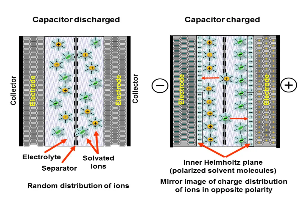
Unlike conventional capacitors, a supercapacitor does not have a dielectric material between its electrodes. The electric double layer that forms on the surfaces of the two electrodes works as the dielectric material and provides capacitance ratings up to several orders of magnitude higher than aluminum electrolytic capacitors. In addition, electrical double layer capacitors have higher power density compared to conventional batteries.
The elementary structure of a supercapacitor consists of an electrolytic solution, two electrodes, and a separator. The two electrodes are made up of a composite material consisting of a high conducting part (metal collector) and a high surface area part (active material). A separator is used to separate these two electrodes. This separator allows ionic conduction between the two electrodes and prevents electronic conduction through physical contact between them. This composite is then folded and stacked into a container. The space between the two electrodes of a supercapacitor is filled with a liquid or solid electrolyte.
The performance of a supercapacitor is greatly dependent on the properties of the electrode material and the electrolyte. The electrodes of this capacitor are fabricated from a porous material with a high surface area. Charge is stored near the boundary between the electrolyte and the electrode material or in the micropores. Carbon aero gel, carbon black, and carbon cloth are commonly used for fabricating electrodes for double layer capacitors.
Some supercapacitors use an aqueous electrolyte while others use an organic electrolyte. The aqueous electrolytes that are commonly used in supercapacitors include sulfuric acid and potassium hydroxide. An aqueous electrolyte has low resistance required for a large power density. Compared to aqueous electrolytes, organic electrolytes have higher resistance and yield a relatively small power density. The most commonly used organic electrolytes are based on acetonitrile or propylene carbonate.
Supercapacitors modules
When designing an ultra-capacitor-based power system, it is critical to consider many factors including the voltage management system, model for the supercapacitor, topology of the power system, and the dynamic terminal behavior. Many manufacturers design customized supercapacitor modules to meet the requirements of a specific application.
Supercapacitors have low cell voltages, typically 0.9to 3.3V, and they are commonly connected in parallel or series to form modules. When connecting supercapacitors in series, it is important to ensure that there is equal distribution of cell voltage.
In applications that demand higher energy and/or power, more than one supercapacitor are required. To deliver the required energy and/or power, supercapacitors are usually connected in parallel. Connecting supercapacitors in parallel increases capacitance and decreases the equivalent series resistance (ESR). This connection is suitable when higher energy and/or power are required.
Most systems require more working voltage than a single supercapacitor can supply. In systems that demand high voltages, supercapacitors are commonly connected in series. This connection decreases the capacitance and increases the ESR. Just like a parallel connection, a series connection delivers higher energy.
When connecting supercapacitors in series, it is critical to ensure that only components with the same part number are used. Connecting dissimilar parts can significantly affect the overall performance of a supercapacitor module. In addition, supercapacitors that are connected in series require a balancing circuit to ensure that there is a voltage balance.
Consider a system in which two supercapacitors with same part number are connected in series. Despite the components being similar, their insulated resistance and capacitance can be different. These variations in capacitance and insulation resistance can cause a voltage imbalance that can lead to overvoltage to one supercapacitor.
Example:
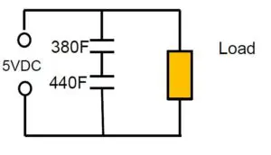
- Series connection of 2pcs 400F 2.5V cells with +10/-5% cap tolerance
- Worst case scenario: a 380F and 440F caps gets on the board
- The voltage of the individual cells will be: 2.68 V: 2.32V
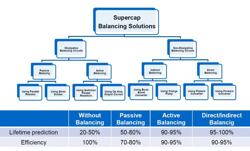
There are two categories of voltage balancing: passive and active balancing. A passive balancing circuit is a simple and inexpensive solution that consists of resistors. It is advisable to use components with low resistance values since they allow faster balancing compared to components with higher values. The lower the resistance value, the higher the speed of voltage balancing.
In applications where circuit loss is a key consideration, then resistors with higher resistance values can be used. Although components with higher resistance values have lower power losses, they lower the speed of voltage balancing. As resistance increases, the circuit loss and the speed of voltage balancing decrease. The impressed voltage of a supercapacitor limits the maximum resistance value that can be used. The maximum resistance value decreases with an increase in impressed voltage. Passive voltage balancing is mostly used in low-duty-cycle systems.
An active balancing circuit is highly effective in equalizing the voltage of cells in a supercapacitor module. These circuits behave nonlinearly and can be implemented in various ways. Most active balancing circuits use an operational amplifier to achieve voltage balance.
Generally speaking, active balancing circuits offer excellent energy efficiency. The power consumed by an active balancing circuit is dependent on the slew rate of the amplifier. Although high-speed amplifiers achieve short-time balance, they are unsuitable for applications where power consumption is a key factor.
In addition to ordinary active balancing circuits, there are dedicated integrated circuits for balancing voltage of supercapacitors. These ICs are designed to achieve high efficiency in voltage balancing. Active balancing circuits provide faster voltage balance and are mostly used in high-duty-cycle applications.
Some applications can expose energy storage devices to extreme temperatures. The performance of battery-based energy storage devices is significantly affected by extreme temperatures. Supercapacitor modules can operate over a wide range of temperatures with minimal effects on their performance and reliability.
Conventional batteries have a shorter operating life compared to supercapacitor-based energy storage devices. The electrochemical reactions that occur in a battery during charge/discharge cycles can cause significant degradation. This degradation limits the number of cycles. In comparison, supercapacitors modules offer excellent durability to cycling since no electrochemical reactions are involved.
Supercapacitors life is however directly impacted by the overvoltage, thus a selection of balancing method may be a critical factor for the supercapacitor module life prediction.
Rule of thumb by lifetime prediction is:
- With every 0.2 voltage decrease the cell lifetime increases about 2x in the specified voltage range
- With every 0.1 voltage increase over the spec V the cell lifetime gets half
Because supercapacitor modules offer higher power densities than ordinary batteries, they can discharge more power, and this makes them a suitable choice for applications where high-peak load leveling and high-power backup are required.
Although supercapacitors offer many advantages over traditional battery-based energy storage devices, they have some drawbacks. To start with, the specific energy of electrical double layer capacitors is lower than that of batteries. Secondly, voltage imbalances in supercapacitor modules can cause significant reductions in available energy and/or premature irreversible deteriorations.
A significant amount of energy is lost when electrical energy is being delivered from the source to the load. Since supercapacitors have low specific energies, they demand more efficient means of delivering the stored energy to minimize wastage. Improvements in supercapacitor technology are expected to provide solutions to some of these drawbacks.
The characteristics of supercapacitor modules make them a suitable choice for a wide spectrum of applications. These modules are common in various applications including hybrid power systems, regenerative braking systems, instantaneous back-up power sources, motor starting systems, LED displays, DC-to-DC converters, and hybrid electric vehicles (HEVs).
Conclusion
Supercapacitors modules offer better coulombic efficiency, cycle life performance, low temperature performance, and power capability as compared to traditional batteries such as lead-acid, lithium-ion, Ni-Cd, and Ni-MH batteries. Supercapacitor-based energy storage devices allow easier estimation of state of charge. In most systems where two or more supercapacitor cells are connected in series, a voltage balancing circuit is required to prevent voltage imbalance. Voltage balancing circuits are broadly categorized into passive and active balancing circuits. The characteristics of supercapacitor modules make them a suitable choice for a wide range of applications including hybrid electric vehicles (HEVs), battery-propelled electric vehicles (BEV), and a variety of industrial applications.


