


Passive Components Blog
No Result
View All Result
  • Home
  • NewsFilter
    • All
    • Aerospace & Defence
    • Antenna
    • Applications
    • Automotive
    • Capacitors
    • Circuit Protection Devices
    • electro-mechanical news
    • Filters
    • Fuses
    • Inductors
    • Industrial
    • Integrated Passives
    • inter-connect news
    • Market & Supply Chain
    • Market Insights
    • Medical
    • Modelling and Simulation
    • New Materials & Supply
    • New Technologies
    • Non-linear Passives
    • Oscillators
    • Passive Sensors News
    • Resistors
    • RF & Microwave
    • Telecommunication
    • Weekly Digest

    Bourns Introduces Automotive Shielded Power Inductors for Compact DC‑DC Converters

    EMC Design Fundamentals: Safe Use of Varistors and Common Mode Chokes in Mains and Data-Line Filters

    Murata Unveils Lead Disc Ceramic Capacitors for Automotive Safety and EMI Suppression

    SCHURTER Releases Intelligent Three‑Terminal Fuses for Safer Li‑ion Battery Systems

    Can Copper Conductive Inks Displace Silver in Hybrid Electronics?

    Square-Wave Harmonics and RMS Currents in Power Converters

    LeanBOM: Practical Cross‑Technology Capacitor Search by Real Working Conditions

    In the Age of AI, Every Watt Counts: Implications for Components

    Stackpole Extends Resistance Range of 2512 High‑Power Current Sense Resistors

    Trending Tags

    • Ripple Current
    • RF
    • Leakage Current
    • Tantalum vs Ceramic
    • Snubber
    • Low ESR
    • Feedthrough
    • Derating
    • Dielectric Constant
    • New Products
    • Market Reports
  • VideoFilter
    • All
    • Antenna videos
    • Capacitor videos
    • Circuit Protection Video
    • Filter videos
    • Fuse videos
    • Inductor videos
    • Inter-Connect Video
    • Non-linear passives videos
    • Oscillator videos
    • Passive sensors videos
    • Resistor videos

    EMC Design Fundamentals: Safe Use of Varistors and Common Mode Chokes in Mains and Data-Line Filters

    Ferrite versus Nanocrystalline Power Inductor Cores: Turns, Gap and Size

    KYOCERA AVX Presents Antenna Integrator Studio Tutorial for Antenna Placement and RF Design

    Power Design Simulation Tools for Faster Inductor Selection and Loss Optimization

    EMC‑Compliant PCB and Connector Design Guidelines

    Why Isolated DC/DC Power Supplies Fail Late, Würth Elektronik Podcast

    Designing 800 V DC EMC Filters: Calculation, Simulation and Measurement

    Current Sense Transformer Datasheet and Design‑in Guide

    Designing a USB Type‑C Flyback Planar Transformer with Frenetic’s Planar Tool

    Trending Tags

    • Capacitors explained
    • Inductors explained
    • Resistors explained
    • Filters explained
    • Application Video Guidelines
    • EMC
    • New Products
    • Ripple Current
    • Simulation
    • Tantalum vs Ceramic
  • Knowledge Blog
  • Dossiers
    • AI Hardware Dossier
    • Power Converter Dossier
    • Automotive Dossier
    • Capacitor Dossier
    • Resistor Dossier
    • Inductor Dossier
    • Circuit Protection Dossier
  • Suppliers
    • Who is Who
  • PCNS
    • PCNS 2025
    • PCNS 2023
    • PCNS 2021
    • PCNS 2019
    • PCNS 2017
  • Events
  • Home
  • NewsFilter
    • All
    • Aerospace & Defence
    • Antenna
    • Applications
    • Automotive
    • Capacitors
    • Circuit Protection Devices
    • electro-mechanical news
    • Filters
    • Fuses
    • Inductors
    • Industrial
    • Integrated Passives
    • inter-connect news
    • Market & Supply Chain
    • Market Insights
    • Medical
    • Modelling and Simulation
    • New Materials & Supply
    • New Technologies
    • Non-linear Passives
    • Oscillators
    • Passive Sensors News
    • Resistors
    • RF & Microwave
    • Telecommunication
    • Weekly Digest

    Bourns Introduces Automotive Shielded Power Inductors for Compact DC‑DC Converters

    EMC Design Fundamentals: Safe Use of Varistors and Common Mode Chokes in Mains and Data-Line Filters

    Murata Unveils Lead Disc Ceramic Capacitors for Automotive Safety and EMI Suppression

    SCHURTER Releases Intelligent Three‑Terminal Fuses for Safer Li‑ion Battery Systems

    Can Copper Conductive Inks Displace Silver in Hybrid Electronics?

    Square-Wave Harmonics and RMS Currents in Power Converters

    LeanBOM: Practical Cross‑Technology Capacitor Search by Real Working Conditions

    In the Age of AI, Every Watt Counts: Implications for Components

    Stackpole Extends Resistance Range of 2512 High‑Power Current Sense Resistors

    Trending Tags

    • Ripple Current
    • RF
    • Leakage Current
    • Tantalum vs Ceramic
    • Snubber
    • Low ESR
    • Feedthrough
    • Derating
    • Dielectric Constant
    • New Products
    • Market Reports
  • VideoFilter
    • All
    • Antenna videos
    • Capacitor videos
    • Circuit Protection Video
    • Filter videos
    • Fuse videos
    • Inductor videos
    • Inter-Connect Video
    • Non-linear passives videos
    • Oscillator videos
    • Passive sensors videos
    • Resistor videos

    EMC Design Fundamentals: Safe Use of Varistors and Common Mode Chokes in Mains and Data-Line Filters

    Ferrite versus Nanocrystalline Power Inductor Cores: Turns, Gap and Size

    KYOCERA AVX Presents Antenna Integrator Studio Tutorial for Antenna Placement and RF Design

    Power Design Simulation Tools for Faster Inductor Selection and Loss Optimization

    EMC‑Compliant PCB and Connector Design Guidelines

    Why Isolated DC/DC Power Supplies Fail Late, Würth Elektronik Podcast

    Designing 800 V DC EMC Filters: Calculation, Simulation and Measurement

    Current Sense Transformer Datasheet and Design‑in Guide

    Designing a USB Type‑C Flyback Planar Transformer with Frenetic’s Planar Tool

    Trending Tags

    • Capacitors explained
    • Inductors explained
    • Resistors explained
    • Filters explained
    • Application Video Guidelines
    • EMC
    • New Products
    • Ripple Current
    • Simulation
    • Tantalum vs Ceramic
  • Knowledge Blog
  • Dossiers
    • AI Hardware Dossier
    • Power Converter Dossier
    • Automotive Dossier
    • Capacitor Dossier
    • Resistor Dossier
    • Inductor Dossier
    • Circuit Protection Dossier
  • Suppliers
    • Who is Who
  • PCNS
    • PCNS 2025
    • PCNS 2023
    • PCNS 2021
    • PCNS 2019
    • PCNS 2017
  • Events
No Result
View All Result
Passive Components Blog
No Result
View All Result

KYOCERA AVX Extends Ultra‑Broadband RF Capacitor Series

24.2.2026
Reading Time: 7 mins read
A A

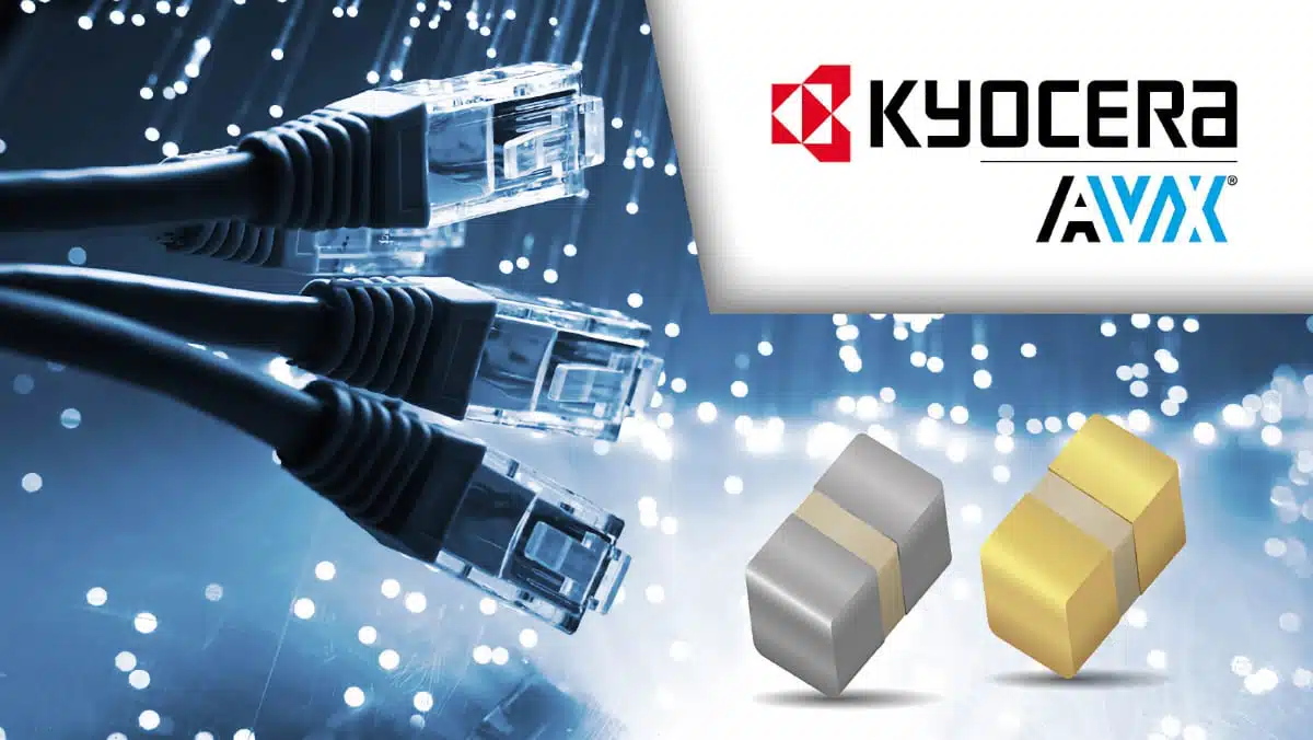
Kyocera AVX has extended its 550/560 Series ultra‑broadband RF capacitors (UBC) with four new components aimed at high‑speed, high‑bandwidth optical communication systems and RF front ends.

The additions bring higher working voltages and more capacitance options in the compact 0402 footprint, helping design engineers improve signal integrity while saving PCB real estate in dense optical and RF modules.

RelatedPosts

KYOCERA AVX Presents Antenna Integrator Studio Tutorial for Antenna Placement and RF Design

KYOCERA AVX Releases NTN Antenna Selection Guide Brochure

KYOCERA 10 µF 0201 MLCC Brings High‑Capacitance into Mobile Designs

Key features and benefits

KYOCERA AVX’s UBC ceramic capacitor construction family is positioned as a wideband, low‑loss solution for RF, microwave, and optical communication circuits that must operate from kilohertz through millimeter‑wave frequencies. The latest extension targets designers who need higher voltage margins and more flexibility in impedance matching and broadband decoupling.

Key characteristics of the extended 550/560 Series UBC range include:

  • Frequency coverage from approximately 7 kHz up to 110 GHz, suitable for broadband RF/microwave and optical front‑end use.
  • Capacitance values spanning 1 nF to 220 nF in the overall series, with four new 0402 parts added at 1 nF, 10 nF, 22 nF, and 47 nF.
  • Maximum working voltage rating extended from 16 V up to 100 V in the new parts, supporting higher signal swings and bias levels.
  • Operating temperature range from −55 °C to +125 °C, compatible with typical telecom, datacom, and industrial environments.
  • Compact SMD packages, including 0402 case size for the new releases, supporting dense layouts and short RF paths.
  • Designed for high signal integrity with high reliability, high precision, and ultra‑low insertion loss over the specified frequency range.

In practice, the combination of high capacitance at small size, wide frequency coverage, and higher working voltage allows a single capacitor type to cover multiple roles: broadband DC blocking, AC coupling, and decoupling in high‑speed optical and RF systems. This reduces the number of different capacitor types on the BOM and simplifies matching networks, which is attractive for purchasing and platform‑level design reuse.

Typical applications

The expanded UBC range targets high‑speed data transmission, especially where optical links and RF/microwave circuitry intersect. Typical use cases called out by the manufacturer include:

  • Transimpedance amplifiers (TIA) in optical receivers, where low‑loss AC coupling and decoupling are critical for noise performance.
  • Receive and transmit optical subassemblies (ROSA/TOSA), including pluggable optical modules.
  • Synchronous optical networks (SONET) and related telecom backhaul equipment.
  • Broadband and RF test and measurement equipment that must maintain flat response and low distortion over wide bandwidths.
  • Vertical cavity surface emitting lasers (VCSEL) drivers and associated high‑speed digital front ends.
  • Fiber‑optic communication systems and high‑speed serializer/deserializer (SerDes) interfaces.
  • Analog and digital RF front ends for 5G and satellite communication networks.
  • High‑resolution sensing, imaging, and radar systems used in industrial automation, security screening, and driverless/assisted driving platforms.

In many of these systems, designers face the challenge of maintaining consistent impedance and low return loss across decades of frequency. Ultra‑broadband capacitors with controlled behavior up to 110 GHz can significantly simplify matching networks and bias‑tee designs compared to general‑purpose MLCCs, which tend to exhibit strong self‑resonance and loss peaks.

Technical highlights

From a component selection perspective, the extended 550/560 UBC series is notable for a few technical points that differentiate it from conventional chip capacitors:

  • Very wide usable frequency range: The specified 7 kHz to 110 GHz bandwidth allows a single capacitor type to bridge low‑frequency bias/decoupling needs and very high‑frequency RF functions. This is especially relevant for broadband amplifiers, RF sampling front ends, and wideband test fixtures.
  • High working voltage headroom: Increasing the series maximum working voltage from 16 V to 100 V in the new part numbers reduces the risk of over‑voltage in systems with higher bias rails or large RF swings. This is important in line‑powered optical modules, power‑over‑fiber interfaces, or RF power stages where traditional low‑voltage UBCs could be a limitation.
  • Expanded 0402 capacitance set: Adding 1 nF, 10 nF, 22 nF, and 47 nF in 0402 gives RF designers more granularity when tuning broadband impedance or designing compact bias‑tees. 0402 is a common compromise between minimal parasitics and assembly robustness.
  • Tight and controlled tolerances: The series covers capacitance tolerances from ±10% up to ±100% depending on value and part type, with the tighter bins suitable for precision matching and equalization networks.
  • Temperature range and stability: The −55 °C to +125 °C operating range supports deployment in telecom shelters, base stations, industrial environments, and equipment racks with limited cooling. For exact dielectric type and detailed capacitance versus temperature behavior, designers should refer to the manufacturer datasheet.

Compared with standard high‑frequency MLCCs, UBC parts are optimized not just for low ESR at a single band, but for predictable impedance and ultra‑low insertion loss over a very broad spectrum. This often justifies their use in critical RF signal paths even if the unit price is higher than generic MLCC options.

With the latest extension, the 550/560 Series UBC portfolio now comprises a total of 15 part numbers. The four new devices are 0402 case size parts with capacitance values of 1 nF, 10 nF, 22 nF, and 47 nF and a maximum working voltage of up to 100 V.

Design‑in notes for engineers

When designing in the 550/560 Series ultra‑broadband capacitors, a few practical points can help extract the intended RF performance:

  • Treat the capacitor as a transmission‑line component at higher frequencies. Pad geometry, via placement, and reference planes should be optimized to minimize additional parasitic inductance and capacitance that could spoil the ultra‑broadband behavior.
  • Use manufacturer‑provided S‑parameter data. For accurate simulation of insertion loss, return loss, and group delay up to tens of GHz, import the official S‑parameter models into your RF CAD/EM tools rather than relying on ideal capacitor models.
  • Pay attention to voltage derating. Even though the new parts extend working voltage up to 100 V, it is good practice to apply derating in applications with high RF swing, transient exposure, or elevated temperatures. The appropriate derating curve should be taken from the datasheet.
  • Consider thermal environment. While the −55 °C to +125 °C rating covers most telecom and industrial uses, hotspots on densely packed PCBs (especially near laser drivers or power amplifiers) can locally raise temperature. Placement near airflow or heatsinks may be beneficial in tightly integrated optical modules.
  • Implement good grounding and decoupling practices. When using UBCs for broadband decoupling or bias‑tees, pair them with solid ground planes and short return paths to avoid unintended resonances. It can be effective to combine different capacitance values in parallel to flatten impedance over the target band.
  • Coordinate with test engineering. Because these parts are often used at the boundary between RF and optical domains, early coordination with test engineers on fixture design and de‑embedding can avoid characterization issues and re‑spins.

For purchasing teams, the key benefit of the extended UBC range is a broader set of drop‑in options within the same qualified family. This can reduce second‑source complexity and simplify maintaining common platforms across different optical module generations or RF product variants.

Source

This article is based on information from an official Kyocera AVX press release and associated product details. For precise ratings, electrical characteristics, and full part number definitions, always refer to the current manufacturer datasheet and product pages.


References

  1. Kyocera AVX press release – New capacitors for optical communications (UBC Series extension)
  2. Kyocera AVX – Corporate website

Related

Recent Posts

Murata Unveils Lead Disc Ceramic Capacitors for Automotive Safety and EMI Suppression

15.7.2026
29

Square-Wave Harmonics and RMS Currents in Power Converters

14.7.2026
27

LeanBOM: Practical Cross‑Technology Capacitor Search by Real Working Conditions

14.7.2026
34

In the Age of AI, Every Watt Counts: Implications for Components

13.7.2026
48

RF Filters and Passive Components Enabling the 7 Missile RF Subsystems

9.7.2026
52

From DCL to SSC: Bridging Electrical Symptoms and Structural Indicators in Tantalum Capacitors

7.7.2026
61

High-Q RF & Microwave MLCCs: A Cross-Vendor Benchmark

2.7.2026
94

TAIYO YUDEN Introduced Hybrid Aluminum Capacitors for 48V Automotive Power Supplies

2.7.2026
80

YAGEO Announces July 2026 Capacitor Price Increase

1.7.2026
836

Upcoming Events

Jul 21
16:00 - 17:00 CEST

Safety by design: X and Y Interference suppression capacitors for power line filters

Jul 28
8:00 - 11:00 CEST

Post Procurement Testing of EEE Components for LEO Space Applications

Jul 29
17:30 - 18:30 CEST

To Ferrite or to Nanocrystalline in Transformer Design

View Calendar

Popular Posts

  • Boost Converter Design and Calculation

    0 shares
    Share 0 Tweet 0
  • Buck Converter Design and Calculation

    0 shares
    Share 0 Tweet 0
  • YAGEO Announces July 2026 Capacitor Price Increase

    0 shares
    Share 0 Tweet 0
  • Flyback Converter Design and Calculation

    0 shares
    Share 0 Tweet 0
  • LLC Resonant Converter Design and Calculation

    0 shares
    Share 0 Tweet 0
  • MLCC and Ceramic Capacitors

    0 shares
    Share 0 Tweet 0
  • Earthing Systems and IEC Classification Explained

    0 shares
    Share 0 Tweet 0
  • Nvidia Vera Rubin: Why One AI Rack Needs So Many More MLCC Capacitors

    0 shares
    Share 0 Tweet 0
  • MLCCs in the Age of AI: Q2 2026 Market Tightness

    0 shares
    Share 0 Tweet 0
  • Dual Active Bridge (DAB) Topology

    0 shares
    Share 0 Tweet 0

Newsletter Subscription


Passive Components Blog

© EPCI - Leading Passive Components Educational and Information Site

  • Home
  • Privacy Policy
  • EPCI Membership & Advertisement
  • About

No Result
View All Result
  • Home
  • Knowledge Blog
  • Dossiers
  • PCNS

© EPCI - Leading Passive Components Educational and Information Site

This website uses cookies. By continuing to use this website you are giving consent to cookies being used. Visit our Privacy and Cookie Policy.
Go to mobile version