


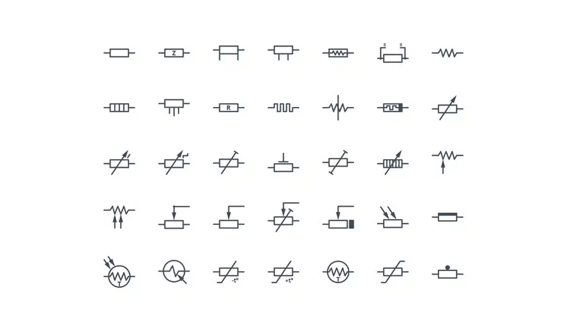
There are number of resistor components and symbols. Here we are providing overview of standard but also some unusual symbols related to resistive products.
There are two symbols standards used in USA/Japan (NEMA) “zig-zag” style and IEC “new boxed” style used in Europe.
Standard Resistor Symbols
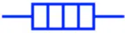
Resistor (NEMA & IEC Systems)
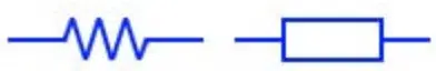
It is the symbol of a fixed resistor. Both of these symbols represent a fixed resistor in NEMA (left) & IEC (right) standards systems.
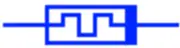
Attenuator
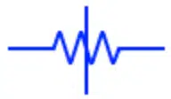
An attenuator works opposite to the amplifier. It reduces the power of the signal without distorting it. It dissipates the signal’s power within its own resistor network. The symbol of attenuator is given above.
Preset Resistor
It is a variable resistor whose resistance is adjusted during manufacturing or designing of the circuit. It is not changed during normal use of the circuit. The resistance of preset resistor is changed using a screwdriver.
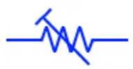
Non Reactive Resistor

These resistors, also known as non-inductive resistors, have pure resistance. A common wire wound resistor has inductance due to the magnetic field produced by the winding. Non-reactive resistors have special winding designs to cancel each other’s magnetic fields.
Impedance

The impedance is a complex quantity made of real & imaginary part. The real part represent the resistance & the imaginary part represents the reactance.
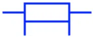
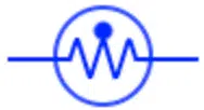
Heating Element
This component converts the electrical energy into heat energy. The current flow through the heating element generates heat energy due to its resistance.
Protective Resistor

These both symbols represent a protection resistor. It operates like a resistor that limits the current flow & if the current exceeds its certain limit then it blow out opening the circuit.
Memristor
Memristor or also known as memory resistor is a hypothetical non-volatile memory component whose resistance depends on the current that has been passed through it in the past. It remembers its last known resistance when it is Powered OFF/ON.
Shunt Resistor
A shunt resistor (also known as current shunt) is a resistor with low & precise resistance used to measure the current through it. The current is measured by the voltage drop across it. Thus it acts as a current sensor.
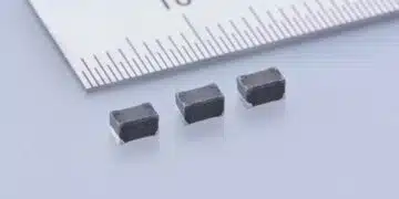
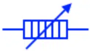
Resistor Array
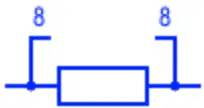
Resistor array is a combination of multiple resistors in a single packaging. It contains multiple individual resistors denoted by the number in the symbols e.g 8 in this case. The resistors are not connected together except for its one side which is connected with VCC for pull up & GND for pull down. They are used for saving space & cost of placing.
Variable & Adjustable Resistor Symbols
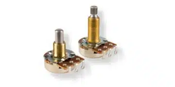
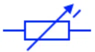
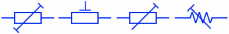
Variable Resistor
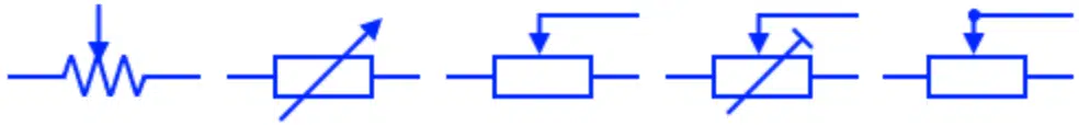
A variable resistor also known as potentiometer or rheostate has a variable resistance. It has three terminals. The two of them have fixed resistance while the third terminal move over the resistive trace or wire to increase or decrease the resistance. They are used for increasing or decreasing the current flow in a circuit during its normal operation.
Continuous Variable Resistor
Such type of variable resistor has a continuous resistance i.e. the sliding or rotating the contact gives out a continuous value of resistance. It can achieve infinite numbers of resistance values ranging from min to max.
Step Variable Resistor
This type of variable resistor’s resistance increase or decreases in steps . The contacts does not slide smoothly but jumps from steps . Each step movement increase or decrease a fixed amount of resistance.
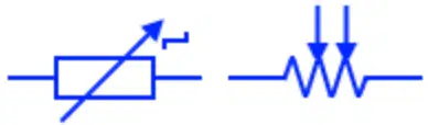
Carbon Pile Variable resistor
This type of variable resistor is made up of carbon discs clamped together between two metal plates. Increasing or decreasing the pressure between these metal plates increases the resistance of the device.
Variable Resistor with ON/OFF switch
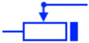
This type of variable resistor has a built-in switch that breaks or make the contact between the two terminals.
Preset Resistor
Preset resistor is a variable resistor that is only operated during manufacturing and tuning a circuit. they are not operated during the normal use of a circuit. there design are not as rigid as a variable resitors (Potentiometer etc).
Special Resistor Symbols
Photo resistor Light Dependent Resistor LDR
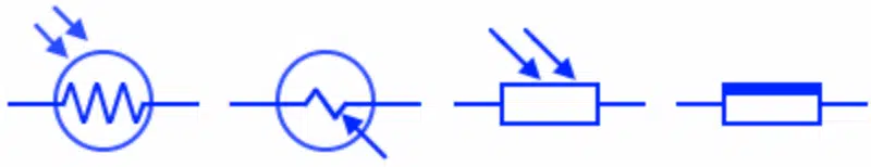
It is a light dependent resistor i.e. its resistance depends on the intensity of the light. The resistance of LDR decreases with increase in the light intensity.
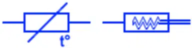
Thermistor

Thermistor or thermal resistor is a type of resistor whose resitance depends on its surrounding temperature. It either decrease or increase with the temperature depnding on the type of thermistor.
NTC & PTC Thermistor
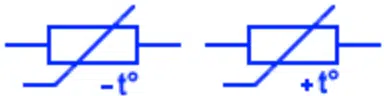
NTC stands for negative temperature coefficient & PTC stands for positive temperature coefficient. The NTC Thermistor resistance decrease with increase in the temperature & denoted by –t° sign. The PTC thermistor resistance increase with increase in temperature & denoted by +t° sign.
Varistor VDR
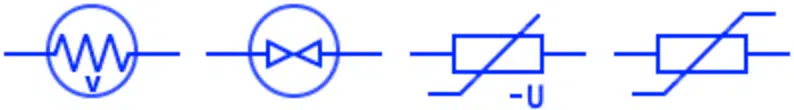
Varistor or VDR (voltage dependent resistor) is a type of resistor whose resistance depends on the voltage applied. Its resistance varies with the change in the applied voltage. These symbols (some of them are old & new) represent varistor.
Iron Hydrogen Resistor
It is positive temperature coefficient resistor made of iron wire inside hydrogen filled bulb. Its resistance increase with temperature which is due to the increase in the current flow. The increasing resistance opposes the increase in current. Thus they are used in stabilizing circuit.
Magneto Resistor

Magneto resistor or MDR (Magnetic dependent resistor) is a type of resistor whose resistance depends on the external magnetic field. It resistance changes with change in magnetic field intensity & It is a used as a magnetic sensor for sensing magnetic field.
Resistance thermometer or RTD
Resistance temperature detector (RTD) is a temperature sensor whose electrical resistance changes with the temperature. The material used in RTD’s has very accurate relation between the resistance & temperature. It can be measured by supply of constant current & the voltage drop across the resistor.