Passive Components Blog
No Result
View All Result
  • Home
  • NewsFilter
    • All
    • Aerospace & Defence
    • Antenna
    • Applications
    • Automotive
    • Capacitors
    • Circuit Protection Devices
    • electro-mechanical news
    • Filters
    • Fuses
    • Inductors
    • Industrial
    • Integrated Passives
    • inter-connect news
    • Market & Supply Chain
    • Market Insights
    • Medical
    • Modelling and Simulation
    • New Materials & Supply
    • New Technologies
    • Non-linear Passives
    • Oscillators
    • Passive Sensors News
    • Resistors
    • RF & Microwave
    • Telecommunication
    • Weekly Digest

    Bourns Extends Rotational Life Option for its Guitar Potentiometer

    Modeling and Simulation of Leakage Inductance

    Power Inductor Considerations for AI High Power Computing – Vishay Video

    TAIYO YUDEN Releases Compact SMD Power Inductors for Automotive Application

    Fischer Releases High Vibration Robust Ratchet Locking USB-C Connector System

    Littelfuse Unveils High-Use Tactile Switches with 2 Million Cycle Lifespan

    KYOCERA AVX Releases Compact High-Directivity Couplers

    Supercapacitors Emerge as a Promising Solution to AI-Induced Power Energy Spikes

    Wk 18 Electronics Supply Chain Digest

    Trending Tags

    • Ripple Current
    • RF
    • Leakage Current
    • Tantalum vs Ceramic
    • Snubber
    • Low ESR
    • Feedthrough
    • Derating
    • Dielectric Constant
    • New Products
    • Market Reports
  • VideoFilter
    • All
    • Antenna videos
    • Capacitor videos
    • Circuit Protection Video
    • Filter videos
    • Fuse videos
    • Inductor videos
    • Inter-Connect Video
    • Non-linear passives videos
    • Oscillator videos
    • Passive sensors videos
    • Resistor videos

    Modeling and Simulation of Leakage Inductance

    Power Inductor Considerations for AI High Power Computing – Vishay Video

    Coupled Inductors in Multiphase Boost Converters

    VPG Demonstrates Precision Resistor in Cryogenic Conditions

    Comparison Testing of Chip Resistor Technologies Under High Vibration

    EMC Challenges for High Speed Signal Immunity and Low EMI

    MOSFET Gate Drive Resistors Power Losses

    Modified Magnetic Reluctance Equivalent Circuit and its Implications

    Improving Common Mode Noise Reduction while Decreasing BOM

    Trending Tags

    • Capacitors explained
    • Inductors explained
    • Resistors explained
    • Filters explained
    • Application Video Guidelines
    • EMC
    • New Products
    • Ripple Current
    • Simulation
    • Tantalum vs Ceramic
  • Knowledge Blog
  • Suppliers
    • Who is Who
  • Events
No Result
View All Result
Passive Components Blog
No Result
View All Result

Understanding capacitor ESR in electrolytic capacitors

1.6.2022
Reading Time: 6 mins read
A A

Today’s microprocessor-based systems require power sources that deliver high current and ultra-fast transient performance, with tight regulation.  This creates a need for cost-effective, compact capacitors with high capacitance values. Electrolytic capacitors are the solution of choice but it’s important to go beyond specifying capacitance and voltage to consider equivalent series resistance (ESR) as a figure of merit.

ESR: Easier to define than specify

RelatedPosts

KEMET Design it Day: Capacitors and Inductors Selection Guide for Decoupling And Filtering

How to determine and measure MLCC ripple current and ESR

Degradation of ESR in Polymer Tantalum Capacitors during High Temperature Storage BEST PAPER AWARD

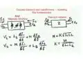
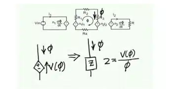
The capacitor equivalent circuit comprises four elements (Figure 1, right): capacitance, equivalent series inductance (ESL) – the sum of inductive elements including leads, a high-resistance DC path (Rp) in parallel with the capacitance, and equivalent series resistance (ESR) – the series resistive effects combined into a single element.

ESR is frequency-dependent, temperature-dependent, and changes as components age. It is usually only an important consideration in selecting electrolytic capacitors.

Constructing the capacitor

‘Wet’ aluminium electrolytic capacitors have an anode plate comprising an electrochemically-etched aluminium foil, a dielectric formed as an oxide layer on this foil, a paper spacer to hold conductive fluid that forms the cathode, and a second foil that connects the electrolyte and the device’s terminal.

Fluid electrolyte penetrates the pores of the oxidised anode foil, so contact area, and hence capacitance, are maximised. The electrolyte’s temperature-dependent conductivity is a major contributor to ESR. Ohmic losses produced by the aluminium oxide layer are frequency-dependent, reducing as frequency increases. Fluid electrolyte is lost over time by vaporisation and diffusion, causing a gradual reduction in the amount of conducting material, reducing the contact area, increasing the ESR and reducing capacitance.
This “drying out” process is temperature dependent and accelerates in components used at higher temperatures or subjected to higher ripple currents, which dissipate more heat as part of their circuit function.

In aluminium electrolytics, ESR falls as temperature increases – its effects reduce as assemblies warm up.

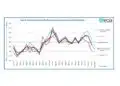
Drying out is irrelevant in solid aluminium electrolytics, or ‘hybrid’ capacitors, where a polymerised organic semiconductor material replaces liquid electrolyte. This technology exhibits a specific conductance of around 10,000 times that of a liquid electrolyte. As Figure 2 shows, overall equivalent series resistance is reduced substantially, most significantly at low temperatures.

Tantalum technology

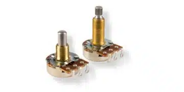
Tantalum capacitor electrolytics have tantalum anodes of either sintered powder, or plain or etched foil. The insulator is an oxide layer on the anode surface. In foil devices the second conductor is an electrolyte held in a spacer. A deposit of manganese dioxide covers the oxide layer in solid versions.

The component’s terminations are substantial contributors to ESR. In a solid capacitor the manganese dioxide is commonly covered with carbon and then a metal such as silver, which is soldered to the negative lead or case. In the foil style, the positive connection is a welded nickel or steel wire connected to a tantalum wire on the anode. Such devices also contain a second tantalum foil in contact with the electrolyte.
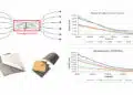
At low frequencies, the oxide losses are most significant. But their contribution decreases inversely with frequency, eventually becoming small compared with the contact material resistance (Figure 3).

Figure 3: Typical relationship beween ESR and frequency for tantalum capacitors (AVX)

Why is ESR important?

Electrolytic capacitors are used as input buffers to supply energy when the mains input voltage is too low, store energy while an AC/DC converter adapts to a new power level, and prevent switching noise from the converter reaching the power source. On the output of a converter, they act as a filter and current sink for inductive elements, and, in DC/DC conversion, function as an energy buffer when the power output demand changes.

In both cases, losses due to ESR will inhibit a capacitor’s ability to quickly source or sink charge. At the input, increasing ESR increases high frequency noise across the capacitor, decreasing filtering effectiveness. At the output, higher ESR causes more ripple, influencing stability of the control loop.

ESR is particularly important in applications with low duty-cycle, high-frequency current pulses. Here, the ripple voltage due to the ESR will be greater than expected based on capacitance alone, although the negative correlation of ESR with temperature means that ripple decreases as the assembly warms up.

Also, the introduction of a resistive element into what designers may assume is a purely reactive circuit can lead to unexpected shifts in phase response, again affecting stability.

What can be done?

Some capacitors are designed specifically for low-ESR, but manufacturers of aluminium electrolytic capacitors do not specify ESR consistently. The value at 25°C and 100kHz is commonly quoted, with a formula provided to calculate the value at the operating frequency. Some suppliers specify at 120Hz; others leave the designer to calculate the figure at the frequency of interest from the dissipation factor (tan∂) and specified maximum ripple current. Furthermore, for capacitors of comparable size and CV, a device with higher capacitance and lower voltage rating will have lower ESR and ESR tends to be lower for aluminium electrolytic devices with long, thin cases because the resistance of the foil is reduced. Larger overall case sizes can cut ESR too.

Also, several smaller-value components can be used in parallel to achieve lower high-frequency ESR, at the expense of board space.

Other advances

Several manufacturers of aluminium electrolytic capacitors have been combining solid and liquid electrolytes to produce hybrid components with ultra-low ESR (low tens of milliohms), with minimal temperature variation, while increasing withstand voltage and accommodating high ripple current.

As ESR varies with external surface area tantalum capacitor manufacturers produce multi-anode devices for high-reliability markets that may point the way to developments for more mainstream applications.

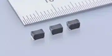
But low ESR is not always the primary consideration and, in a development outside of electrolytic devices, Murata has actually increased ESR of some of its multilayer ceramic chip capacitors, in order to control unwanted resonances that can reduce the decoupling performance at peak frequencies.

Conclusion

There has never been a more diverse range of electrolytic technologies for engineers to choose from. For power applications in particular, the data printed on the component is rarely sufficient to make an informed choice. Talking to an independent specialist that can offer components from a selection of the world’s largest capacitor manufacturers is the surest and quickest route to finding the most appropriate device for any given application.

Written by Adam Chidley Avnet Abacus European Senior Product Manager

Related

Source: AVNET ABACUS

Recent Posts

Modeling and Simulation of Leakage Inductance

9.5.2025
1

Supercapacitors Emerge as a Promising Solution to AI-Induced Power Energy Spikes

6.5.2025
35

Murata and NIMS Built New Database of Dielectric Material Properties

5.5.2025
46

Tariffs Crush Sales Sentiment in April 2025 ECST Results

5.5.2025
61

Solid State Polymer Multilayer Capacitors For High Temperature Application

2.5.2025
32

Graphene-Based BOSC Bank Of Supercapacitor Cells

2.5.2025
13

Hybrid Energy Storage System for Nanosatellite Applications

1.5.2025
9

COTS-Plus Bulk Tantalum Capacitor for LEO Flight Platforms

29.4.2025
38

Shielding Cabinets

29.4.2025
17

Magnetic Shielding and Magnetic Shielding Sheets

29.4.2025
25

Upcoming Events

May 14
11:00 - 12:00 CEST

Reliable RIGID.flex PCBs for Critical Applications – Made in Europe

May 14
17:00 - 17:30 CEST

Calculating Foil Winding Losses with AI

May 28
16:00 - 17:00 CEST

Power Over Data Line

View Calendar

Popular Posts

  • Buck Converter Design and Calculation

    0 shares
    Share 0 Tweet 0
  • Boost Converter Design and Calculation

    0 shares
    Share 0 Tweet 0
  • Flyback Converter Design and Calculation

    0 shares
    Share 0 Tweet 0
  • What is a Dielectric Constant and DF of Plastic Materials?

    4 shares
    Share 4 Tweet 0
  • LLC Resonant Converter Design and Calculation

    0 shares
    Share 0 Tweet 0
  • Ripple Current and its Effects on the Performance of Capacitors

    3 shares
    Share 3 Tweet 0
  • SEPIC Converter Design and Calculation

    0 shares
    Share 0 Tweet 0
  • Dual Active Bridge (DAB) Topology Explained

    0 shares
    Share 0 Tweet 0
  • Solid State Polymer Multilayer Capacitors For High Temperature Application

    0 shares
    Share 0 Tweet 0
  • MLCC Case Sizes Standards Explained

    0 shares
    Share 0 Tweet 0

Newsletter Subscription


Passive Components Blog

© EPCI - Leading Passive Components Educational and Information Site

  • Home
  • Privacy Policy
  • EPCI Membership & Advertisement
  • About

No Result
View All Result
  • Home
  • Knowledge Blog
  • Premium Suppliers

© EPCI - Leading Passive Components Educational and Information Site

This website uses cookies. By continuing to use this website you are giving consent to cookies being used. Visit our Privacy and Cookie Policy.
Go to mobile version