Passive Components Blog
No Result
View All Result
  • Home
  • NewsFilter
    • All
    • Aerospace & Defence
    • Antenna
    • Applications
    • Automotive
    • Capacitors
    • Circuit Protection Devices
    • electro-mechanical news
    • Filters
    • Fuses
    • Inductors
    • Industrial
    • Integrated Passives
    • inter-connect news
    • Market & Supply Chain
    • Market Insights
    • Medical
    • Modelling and Simulation
    • New Materials & Supply
    • New Technologies
    • Non-linear Passives
    • Oscillators
    • Passive Sensors News
    • Resistors
    • RF & Microwave
    • Telecommunication
    • Weekly Digest

    PCNS 2025 Final Program Announced!

    DigiKey Expands Inventory with Over 32,000 Stocking NPIs in Q2 2025

    YAGEO Offers High-Performance Diplexers for Dual-Band Wi-Fi 6E/7Integration

    European Components Distribution (DMASS) Faces Continued Decline in Q2 2025

    TDK Announced Wide Frequency Automotive Wirewound POC Inductors

    Bourns Released Rugged, High-Power TO-247 Thick Film Resistor

    Bourns Announced Shielded Power Inductor with High Saturation and Low Radiation

    Würth Elektronik Expands MagI³C with Variable Step-Down Modules

    KYOCERA AVX Releases 600MHz Band71 Compact SAW Duplexer

    Trending Tags

    • Ripple Current
    • RF
    • Leakage Current
    • Tantalum vs Ceramic
    • Snubber
    • Low ESR
    • Feedthrough
    • Derating
    • Dielectric Constant
    • New Products
    • Market Reports
  • VideoFilter
    • All
    • Antenna videos
    • Capacitor videos
    • Circuit Protection Video
    • Filter videos
    • Fuse videos
    • Inductor videos
    • Inter-Connect Video
    • Non-linear passives videos
    • Oscillator videos
    • Passive sensors videos
    • Resistor videos

    Switched Capacitor Converter Explained

    Understanding Inductor Dot Markings and Their Application in LTspice

    Accelerating Full Bridge LLC Resonant Converter Design with Frenetic AI

    Understanding Switched Capacitor Converters

    Coupled Inductors Circuit Model and Examples of its Applications

    Inductor Resonances and its Impact to EMI

    Highly Reliable Flex Rigid PCBs, Würth Elektronik Webinar

    Causes of Oscillations in Flyback Converters

    How to design a 60W Flyback Transformer

    Trending Tags

    • Capacitors explained
    • Inductors explained
    • Resistors explained
    • Filters explained
    • Application Video Guidelines
    • EMC
    • New Products
    • Ripple Current
    • Simulation
    • Tantalum vs Ceramic
  • Knowledge Blog
  • Suppliers
    • Who is Who
  • Events
No Result
View All Result
Passive Components Blog
No Result
View All Result

AC Line Filters and Insertion Loss Explained

3.1.2024
Reading Time: 3 mins read
A A

A capacitor is a crucial part of all AC line filters, and much of their performance depends on it. The performance of a capacitor to get rid of unwanted electromagnetic signals is usually referred to as insertion loss. On the following pages, we’ll take a closer look at the questions of electromagnetic noise and insertion loss in electric filters.

AC Line Filters’ Primary Purpose Is to Curb EMI

Electromagnetic interference, also shortened as EMI, is an undesired signal that has a negative impact on the electric circuit performance and can even damage it in some cases. There are interferences with both artificial (man-made) and natural origins.

RelatedPosts

PCNS 2025 Final Program Announced!

DigiKey Expands Inventory with Over 32,000 Stocking NPIs in Q2 2025

YAGEO Offers High-Performance Diplexers for Dual-Band Wi-Fi 6E/7Integration

These possible sources of EMI include lightning and storms, solar flares, motors, radar transmitters, power converters and many other devices, including cell phones (there is even a question of their possible disruption of hospital equipment).

A line filter is a device that is meant to reduce the EMI, allowing other devices in the circuit to function properly.

Though most electronic appliances come equipped with their own noise filters, there are cases in which an external filter has to be introduced – for example in unconventional mains.

How does the Whole Thing Work?

A key part in the performance of a filtering circuit is the configuration of elements that make it up, most notably the inductors and capacitors.

The most basic filter, known as the C filter, is made up of just a one feed-through capacitor. Of course, a performance of such a filter is significantly diminished. By increasing the number of inductors and capacitors and combining them in various configurations, much better performance can be achieved.

Insertion Loss and Its Importance in the Filtering Process

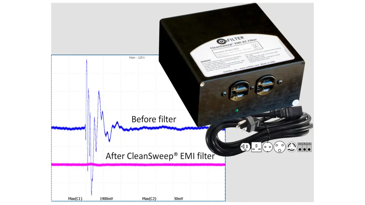
This is one of the chief parameters to take into account when selecting an EMI filter. An EMI filter insertion loss can be summed up as the ratio of before/after voltage once a filter has been introduced. The insertion loss is given in decibels.

There are many factors influencing the insertion loss, such as electrical configuration, circuit and source impedance, load current, and more. Let’s take a look at some of them at least.

Components Configuration

As mentioned previously, the single elements can reduce the EMI somewhat, but most filters will usually consist of several of them. A one-element filter can achieve a 20 dB insertion loss (in theory), but introducing the second element can almost double this number, not to mention adding more.

Naturally, multiple-element filters are then needed whenever a high performance is required.

Circuit Impedance

The performance of the filter is also influenced by the impedances of the source and load. One must always consider these when thinking about the optimal configuration of capacitive and inductive elements.

Load Current

Will also will have its impact on the filter’s insertion loss, based on the quality and material of the filtering parts. For example, when using ferrite inductors, some insertion loss can occur based on which material is used.

Hopefully, by now you have a better understanding of what the AC filters are, what is EMI, what is insertion loss and some factors that affect it. Feel free to elaborate further on this theme in the comments if you’re a specialist in this field – it will be a welcome addition to this article!

Related

Source: Knnit

Recent Posts

PCNS 2025 Final Program Announced!

31.7.2025
3

European Components Distribution (DMASS) Faces Continued Decline in Q2 2025

30.7.2025
5

Würth Elektronik Expands MagI³C with Variable Step-Down Modules

30.7.2025
10

KYOCERA AVX Releases 600MHz Band71 Compact SAW Duplexer

30.7.2025
4

Switched Capacitor Converter Explained

28.7.2025
12

Samsung Releases 1000V 1812 X7R 100nF MLCC for Electric Vehicles

28.7.2025
16

Samsung Electro-Mechanics Releases Molded MLCC Capacitors

28.7.2025
22

Researchers Demonstrated 200C Polymer Film Dielectric

28.7.2025
10

Researchers Demonstrated Zinc-Ion Based Photo-Supercapacitor

28.7.2025
9
Comparative display of a grain size and domain structure; b free energy; c P-E loops after high-entropy ceramics (HECs) and PGS design. source: Nature Communications  ISSN 2041-1723

Researchers Propose Novel MLCC Dielectric Design to Increase Energy Storage Capacity

24.7.2025
38

Upcoming Events

Sep 22
September 22 @ 13:00 - September 25 @ 15:15 EDT

Pre Cap Visual Inspection per Mil-Std-883 (TM 2017)

Sep 30
September 30 @ 12:00 - October 2 @ 14:00 EDT

MIL-Std-883 TM 2010

Oct 17
12:00 - 14:00 EDT

External Visual Inspection per MIL-STD-883 TM 2009

Oct 21
October 21 @ 12:00 - October 23 @ 14:15 EDT

Space and Military Standards for Hybrids and RF Microwave Modules

Nov 4
November 4 @ 12:00 - November 6 @ 14:15 EST

Wirebond Materials, Processes, Reliability and Testing

View Calendar

Popular Posts

  • Buck Converter Design and Calculation

    0 shares
    Share 0 Tweet 0
  • Boost Converter Design and Calculation

    0 shares
    Share 0 Tweet 0
  • Flyback Converter Design and Calculation

    0 shares
    Share 0 Tweet 0
  • LLC Resonant Converter Design and Calculation

    0 shares
    Share 0 Tweet 0
  • What is a Dielectric Constant and DF of Plastic Materials?

    4 shares
    Share 4 Tweet 0
  • Dual Active Bridge (DAB) Topology Explained

    0 shares
    Share 0 Tweet 0
  • Ripple Current and its Effects on the Performance of Capacitors

    3 shares
    Share 3 Tweet 0
  • How to Design an Inductor

    0 shares
    Share 0 Tweet 0
  • MLCC Case Sizes Standards Explained

    0 shares
    Share 0 Tweet 0
  • MLCC and Ceramic Capacitors

    0 shares
    Share 0 Tweet 0

Newsletter Subscription


Passive Components Blog

© EPCI - Leading Passive Components Educational and Information Site

  • Home
  • Privacy Policy
  • EPCI Membership & Advertisement
  • About

No Result
View All Result
  • Home
  • Knowledge Blog
  • Premium Suppliers

© EPCI - Leading Passive Components Educational and Information Site

This website uses cookies. By continuing to use this website you are giving consent to cookies being used. Visit our Privacy and Cookie Policy.
Go to mobile version