Passive Components Blog
No Result
View All Result
  • Home
  • NewsFilter
    • All
    • Aerospace & Defence
    • Antenna
    • Applications
    • Automotive
    • Capacitors
    • Circuit Protection Devices
    • electro-mechanical news
    • Filters
    • Fuses
    • Inductors
    • Industrial
    • Integrated Passives
    • inter-connect news
    • Market & Supply Chain
    • Market Insights
    • Medical
    • Modelling and Simulation
    • New Materials & Supply
    • New Technologies
    • Non-linear Passives
    • Oscillators
    • Passive Sensors News
    • Resistors
    • RF & Microwave
    • Telecommunication
    • Weekly Digest

    DigiKey Announces Back to School Giveaway to Empower Tomorrow’s Innovators

    Ripple Steering in Coupled Inductors: SEPIC Case

    TDK Releases Low Loss Thin-Film Inductors for AI Data Centers

    Samsung Releases Ultra–High-Capacitance 4.7uF 2.5V MLCC in 0201 for AI GPU

    SEPIC Converter with Coupled and Uncoupled Inductors

    Coupled Inductors in SEPIC versus Flyback Converters

    Vishay Releases High Current 3.3 V to 36 V ESD Protection Diodes

    TDK Extends SMT Gate Drive Transformers to 1000 V

    Non-Linear MLCC Class II Capacitor Measurements Challenges

    Trending Tags

    • Ripple Current
    • RF
    • Leakage Current
    • Tantalum vs Ceramic
    • Snubber
    • Low ESR
    • Feedthrough
    • Derating
    • Dielectric Constant
    • New Products
    • Market Reports
  • VideoFilter
    • All
    • Antenna videos
    • Capacitor videos
    • Circuit Protection Video
    • Filter videos
    • Fuse videos
    • Inductor videos
    • Inter-Connect Video
    • Non-linear passives videos
    • Oscillator videos
    • Passive sensors videos
    • Resistor videos

    Ripple Steering in Coupled Inductors: SEPIC Case

    SEPIC Converter with Coupled and Uncoupled Inductors

    Coupled Inductors in SEPIC versus Flyback Converters

    Non-Linear MLCC Class II Capacitor Measurements Challenges

    Percolation Phenomenon and Reliability of Molded Power Inductors in DC/DC converters

    Root Causes and Effects of DC Bias and AC in Ceramic Capacitors

    How to Calculate the Output Capacitor for a Switching Power Supply

    Switched Capacitor Converter Explained

    Understanding Inductor Dot Markings and Their Application in LTspice

    Trending Tags

    • Capacitors explained
    • Inductors explained
    • Resistors explained
    • Filters explained
    • Application Video Guidelines
    • EMC
    • New Products
    • Ripple Current
    • Simulation
    • Tantalum vs Ceramic
  • Knowledge Blog
  • Suppliers
    • Who is Who
  • Events
No Result
View All Result
Passive Components Blog
No Result
View All Result

Accurate Inductor Loss Determination using Würth Elektronik eiSos REDEXPERT

1.3.2018
Reading Time: 2 mins read
A A

source: Würth Elektronik eiSos application note

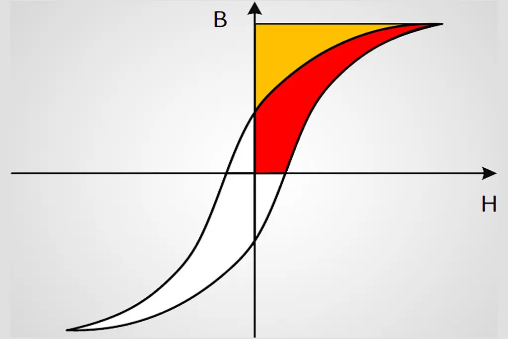
In a Switch Mode Power Supply (SMPS) the majority of any power losses that occur are in the form of switching and magnetic losses. Magnetic loss occurs from the core and the windings in the storage/coupled Inductor. Determination of inductor power loss accurately has become more important to design reliable and efficient systems, especially in the era of green technology. Estimation of core losses in SMPS can require complex measurement set-ups, yet cannot be guaranteed whether the estimation is relevant to the particular application.

RelatedPosts

DigiKey Announces Back to School Giveaway to Empower Tomorrow’s Innovators

Ripple Steering in Coupled Inductors: SEPIC Case

TDK Releases Low Loss Thin-Film Inductors for AI Data Centers

Historically, core losses are calculated using Steinmetz equation and recently with the extension of Steinmetz equations. These equations can estimate losses reliably only for certain conditions or materials. Hence, Würth Elektronik eiSos have developed a state of the art new model to determine core losses effectively and accurately. This model has now implemented in our new design tool REDEXPERT.

 The Würth Elektronik’s AC loss model is accurate and practical model for determining AC losses. The model has been experimentally verified over wide range of frequency, ripple currents and duty cycles and proved to be robust. Due to the fact that this AC loss model is implemented in REDEXPERT, the user does not have to request core loss charts. Overall, REDEXPERT is power online calculation tool saves the engineer’s time in determining the losses and selecting the right component.

Full technical article is available for download here.


Related

Recent Posts

Ripple Steering in Coupled Inductors: SEPIC Case

27.8.2025
2

TDK Releases Low Loss Thin-Film Inductors for AI Data Centers

27.8.2025
3

SEPIC Converter with Coupled and Uncoupled Inductors

26.8.2025
8

Coupled Inductors in SEPIC versus Flyback Converters

26.8.2025
6

TDK Extends SMT Gate Drive Transformers to 1000 V

20.8.2025
20

Non-Linear MLCC Class II Capacitor Measurements Challenges

19.8.2025
39

Researchers Demonstrated HfO Anti-Ferroelectric Flexible Capacitors

19.8.2025
19

Common Mistakes in Flyback Transformer Specs

15.8.2025
49

Littelfuse Unveils High-Precision TMR Angle Magnetic Sensors

13.8.2025
13

High Voltage MLCCs Meeting the Growing Demand for Efficiency in Power Conversion

12.8.2025
157

Upcoming Events

Sep 3
15:30 - 17:30 CEST

How to Choose Your Magnetic Supplier

Sep 16
17:00 - 18:00 CEST

EMI Shielding Challenges

Sep 22
September 22 @ 13:00 - September 25 @ 15:15 EDT

Pre Cap Visual Inspection per Mil-Std-883 (TM 2017)

Sep 30
September 30 @ 12:00 - October 2 @ 14:00 EDT

MIL-Std-883 TM 2010

Oct 17
12:00 - 14:00 EDT

External Visual Inspection per MIL-STD-883 TM 2009

View Calendar

Popular Posts

  • Buck Converter Design and Calculation

    0 shares
    Share 0 Tweet 0
  • Boost Converter Design and Calculation

    0 shares
    Share 0 Tweet 0
  • Flyback Converter Design and Calculation

    0 shares
    Share 0 Tweet 0
  • LLC Resonant Converter Design and Calculation

    0 shares
    Share 0 Tweet 0
  • What is a Dielectric Constant and DF of Plastic Materials?

    4 shares
    Share 4 Tweet 0
  • Ripple Current and its Effects on the Performance of Capacitors

    3 shares
    Share 3 Tweet 0
  • Dual Active Bridge (DAB) Topology Explained

    0 shares
    Share 0 Tweet 0
  • How to Design an Inductor

    0 shares
    Share 0 Tweet 0
  • Core Materials, Permeability and Their Losses

    0 shares
    Share 0 Tweet 0
  • MLCC Case Sizes Standards Explained

    0 shares
    Share 0 Tweet 0

Newsletter Subscription


Passive Components Blog

© EPCI - Leading Passive Components Educational and Information Site

  • Home
  • Privacy Policy
  • EPCI Membership & Advertisement
  • About

No Result
View All Result
  • Home
  • Knowledge Blog
  • Premium Suppliers

© EPCI - Leading Passive Components Educational and Information Site

This website uses cookies. By continuing to use this website you are giving consent to cookies being used. Visit our Privacy and Cookie Policy.
Go to mobile version