Passive Components Blog
No Result
View All Result
  • Home
  • NewsFilter
    • All
    • Aerospace & Defence
    • Antenna
    • Applications
    • Automotive
    • Capacitors
    • Circuit Protection Devices
    • electro-mechanical news
    • Filters
    • Fuses
    • Inductors
    • Industrial
    • Integrated Passives
    • inter-connect news
    • Market & Supply Chain
    • Market Insights
    • Medical
    • Modelling and Simulation
    • New Materials & Supply
    • New Technologies
    • Non-linear Passives
    • Oscillators
    • Passive Sensors News
    • Resistors
    • RF & Microwave
    • Telecommunication
    • Weekly Digest

    October 2025 Interconnect, Passives and Electromechanical Components Market Insights

    Exxelia 4-Terminal Safety Capacitors Compliant with NF F 62-102 Railway Standard

    Wk 43 Electronics Supply Chain Digest

    Samsung Releases Automotive Molded 2220 1kV C0G MLCC

    How to Select Ferrite Bead for Filtering in Buck Boost Converter

    VINATech Offers Smallest 100µF Al-Hybrid Capacitor

    Vishay Unveils SMD 1200V PTC Thermistors in Compact Size

    Power Inductors Future: Minimal Losses and Compact Designs

    Bourns Unveils Automotive 3 Watt Gate Driver Transformer

    Trending Tags

    • Ripple Current
    • RF
    • Leakage Current
    • Tantalum vs Ceramic
    • Snubber
    • Low ESR
    • Feedthrough
    • Derating
    • Dielectric Constant
    • New Products
    • Market Reports
  • VideoFilter
    • All
    • Antenna videos
    • Capacitor videos
    • Circuit Protection Video
    • Filter videos
    • Fuse videos
    • Inductor videos
    • Inter-Connect Video
    • Non-linear passives videos
    • Oscillator videos
    • Passive sensors videos
    • Resistor videos

    How to Select Ferrite Bead for Filtering in Buck Boost Converter

    Power Inductors Future: Minimal Losses and Compact Designs

    Percolation Phenomenon: Degradation of Molded Power Inductors in DC/DC Converters

    Connector PCB Design Challenges

    Efficient Power Converters: Duty Cycle vs Conduction Losses

    Ripple Steering in Coupled Inductors: SEPIC Case

    SEPIC Converter with Coupled and Uncoupled Inductors

    Coupled Inductors in SEPIC versus Flyback Converters

    Non-Linear MLCC Class II Capacitor Measurements Challenges

    Trending Tags

    • Capacitors explained
    • Inductors explained
    • Resistors explained
    • Filters explained
    • Application Video Guidelines
    • EMC
    • New Products
    • Ripple Current
    • Simulation
    • Tantalum vs Ceramic
  • Knowledge Blog
  • Suppliers
    • Who is Who
  • PCNS
    • PCNS 2025
    • PCNS 2023
    • PCNS 2021
    • PCNS 2019
    • PCNS 2017
  • Events
No Result
View All Result
Passive Components Blog
No Result
View All Result

Capacitor Charging and Discharging

22.10.2025
Reading Time: 11 mins read
A A

This article explains capacitor charging, energy content and energy losses during the charge transfer

Capacitor Charging and Discharging

In electronic circuits, charging a capacitor from a voltage source is a common but critical event. Direct connection of an uncharged capacitor to a source can cause dangerously high inrush currents, potentially damaging semiconductors and the capacitor itself. To mitigate this, engineers employ pre-charge circuits with resistors and switches. This paper summarizes insights of capacitor charging dynamics, highlighting the role of resistance, inductance, and their impact on current peaks, oscillations, and energy dissipation.

RelatedPosts

Degradation of Capacitors and its Failure Mechanisms

Backup Capacitors – Supercapacitor

Safety Capacitors

Key Takeaways

  • Capacitor charging involves risks like high inrush currents, necessitating pre-charge circuits to protect components.
  • Resistance and inductance significantly impact current peaks, oscillations, and energy dissipation during charging.
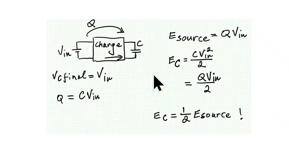
  • Total energy loss during charging is always half of the supplied energy, regardless of circuit configuration.
  • Inductors and diodes can optimize energy storage and reduce losses in capacitor charging circuits.
  • Understanding capacitor charging dynamics is crucial for efficient power electronics design and converter systems.

Basic Charge Storage and Discharge

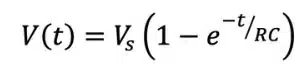
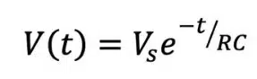
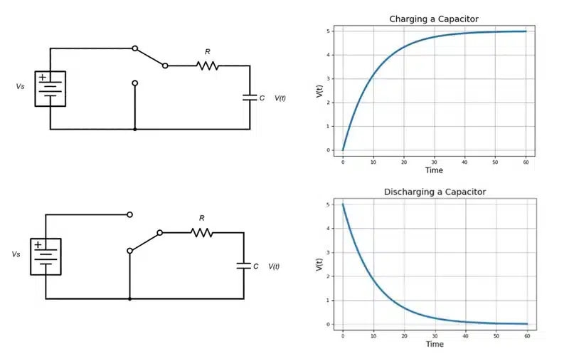
When connected to a direct current (DC) voltage source, capacitors charge almost instantaneously, but they can discharge just as fast if shorted; however, with some resistance in place, the rate of charge and discharge is exponential rather than direct (Figure 1.).

The charging formula is expressed as:

The discharging formula is expressed as:

Oscillators, waveform shapers and low-discharge power backup circuits are examples of electronics that leverage controlled charge and discharge rates.

Figure 1.: Charging capacitor schematic and plotted behavior (top) compared to discharging capacitor schematic and plotted behavior (bottom).source: Knowles Precision Devices Blog

Capacitor Charging Basics

When a capacitor of capacitance C is charged from a voltage source V, the stored energy is:

E = 1 2 C V2

This energy must be supplied by the source, and in a resistive circuit, it is dissipated as heat. Without inductance, the peak current is approximately:

Ipeak = ∆V R

Role of Inductance

Introducing series inductance L changes the dynamics. The circuit becomes an RLC network, and the current follows a damped oscillatory response. The natural resonant frequency is:

ω = 1 LC

As inductance increases, the peak current decreases, but oscillations appear and the charging time extends. Despite these changes, the total energy dissipated in the resistor remains nearly constant.

Impact of Resistance

Sweeping resistance values in simulation revealed that lower resistance increases peak current and oscillations, while higher resistance damps oscillations and reduces peak current. The LC resonance frequency remains unchanged, but the damping factor varies with resistance.

Impact of Insulation Resistance IR and Leakage Current

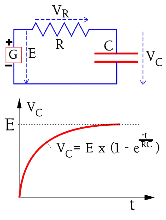
The circuit diagram and charging curve for a capacitor are shown in Figure 2.

C3-11
Figure 2. The charging curve for a capacitor in a resistive circuit

The charging current to the capacitor is shown in Figure 3. (circuit diagram as in Figure 2.). If the capacitor is ideal the current would rapidly attain the limiting value corresponding to the IR. The ideal current curve is designated IC-ideal. But because the polarization in the dielectric requires a finite time for dipoles to reorient the real charging current follows the curve IC-polarization.

C3-12
Figure 3. Ideal and real charging current in a capacitor

Closed-Loop System Considerations

While inductance is beneficial in reducing inrush current, in closed-loop inverter systems it can introduce instability. This occurs because the input of a regulated converter can exhibit negative resistance: as input voltage rises, input current decreases to maintain constant power. Coupled with an LC resonance, this negative resistance may lead to oscillations and instability.

Fundamental Loss Analysis

Simulation and theoretical analysis show that regardless of resistance or inductance, the energy dissipated during charging converges to the same value: half of the supplied energy. This is explained by charge conservation:

the source delivers

Esource = Q · Vin

while the capacitor stores only half of that energy, with the remainder dissipated as heat.

The Diode–Inductor Case

Introducing an inductor and diode changes the dynamics. The inductor stores energy losslessly, and the diode enforces unidirectional current. In this case, the capacitor voltage can rise above the source voltage, approaching twice Vin for very low resistance. As a result, the capacitor stores more energy, and the fraction lost in resistive elements decreases. This explains why measured losses are lower in high‑Q inductor–diode circuits.

Educational Implications

The analysis highlights a key paradox: while direct charging always wastes half the energy, clever circuit arrangements can reduce losses. This principle underpins boost converters, resonant switched‑capacitor converters, and energy recovery techniques. Understanding these fundamentals is essential for efficient power electronics design.

Conclusion

Capacitor charging dynamics are governed by the interplay of resistance, inductance, and capacitance. For practical design, pre-charge circuits with resistors are essential, and inductance must be carefully considered—beneficial for limiting current, but potentially destabilizing in closed-loop systems. Understanding these trade-offs is crucial for robust power electronics design.

Capacitor charging losses are an unavoidable reality in direct RC/RLC circuits, with half of the supplied energy always dissipated. However, by introducing inductors and diodes, designers can alter the voltage dynamics and reduce losses significantly. This knowledge is not only academically interesting but also practically relevant to modern converter design, energy harvesting, and efficient power management systems.

Frequently Asked Questions about Capacitor Charging and Discharging

Why does direct capacitor charging cause high inrush currents?

When an uncharged capacitor is directly connected to a voltage source, it initially behaves like a short circuit. This results in very high inrush currents that can damage semiconductors and the capacitor itself.

How do pre-charge resistors help protect circuits?

Pre-charge resistors limit the initial charging current, reducing stress on components and preventing damage during capacitor charging.

What role does inductance play in capacitor charging?

Series inductance reduces peak current but introduces oscillations. While it can help limit inrush current, in closed-loop inverter systems it may cause instability due to negative input resistance.

Why is half of the supplied energy always lost in direct RC/RLC charging?

In direct charging, only half of the supplied energy is stored in the capacitor. The other half is dissipated as heat in resistive elements, regardless of resistance or inductance values.

How can energy losses be reduced in capacitor charging?

By using inductors and diodes, designers can alter voltage dynamics. This allows the capacitor to store more energy and reduces resistive losses, forming the basis of boost converters and energy recovery circuits.

How to Safely Charge a Capacitor in Power Electronics

  1. Assess the circuit requirements

    Determine the capacitance, voltage source, and expected current levels before connecting the capacitor.

  2. Use a pre-charge resistor

    Insert a resistor in series with the capacitor to limit inrush current and protect sensitive components.

  3. Consider inductance effects

    Add series inductance if needed to reduce current peaks, but be cautious of oscillations in closed-loop systems.

  4. Monitor energy dissipation

    Remember that in direct RC/RLC charging, half of the supplied energy is always lost as heat. Plan for thermal management.

  5. Optimize with inductor-diode circuits

    Use an inductor and diode arrangement to reduce losses and increase stored energy, as in boost converters and resonant switched-capacitor designs.

Related

Recent Posts

Exxelia 4-Terminal Safety Capacitors Compliant with NF F 62-102 Railway Standard

27.10.2025
18

Samsung Releases Automotive Molded 2220 1kV C0G MLCC

23.10.2025
39

How to Select Ferrite Bead for Filtering in Buck Boost Converter

23.10.2025
35

VINATech Offers Smallest 100µF Al-Hybrid Capacitor

23.10.2025
34

Power Inductors Future: Minimal Losses and Compact Designs

22.10.2025
40

Percolation Phenomenon: Degradation of Molded Power Inductors in DC/DC Converters

21.10.2025
44

Murata Integrates Component Models into Cadence EDA Tools

21.10.2025
42

High Energy Density Polymer Film Capacitors via Molecular and Interfacial Design

15.10.2025
27

KYOCERA AVX Expands Stacked MLCC Capacitors Offering

14.10.2025
47

Over-Voltage Protection Clippers, Clampers, Snubbers, DC Restorers

13.10.2025
39

Upcoming Events

Oct 30
11:00 - 12:00 CET

Space Ceramic Capacitors with Flexible Testing

Nov 4
10:00 - 11:00 PST

Design and Stability Analysis of GaN Power Amplifiers using Advanced Simulation Tools

Nov 4
November 4 @ 12:00 - November 6 @ 14:15 EST

Wirebond Materials, Processes, Reliability and Testing

View Calendar

Popular Posts

  • Buck Converter Design and Calculation

    0 shares
    Share 0 Tweet 0
  • Boost Converter Design and Calculation

    0 shares
    Share 0 Tweet 0
  • Flyback Converter Design and Calculation

    0 shares
    Share 0 Tweet 0
  • LLC Resonant Converter Design and Calculation

    0 shares
    Share 0 Tweet 0
  • Ripple Current and its Effects on the Performance of Capacitors

    3 shares
    Share 3 Tweet 0
  • SEPIC Converter Design and Calculation

    0 shares
    Share 0 Tweet 0
  • What is a Dielectric Constant and DF of Plastic Materials?

    4 shares
    Share 4 Tweet 0
  • Dual Active Bridge (DAB) Topology

    0 shares
    Share 0 Tweet 0
  • MLCC and Ceramic Capacitors

    0 shares
    Share 0 Tweet 0
  • Flying Capacitors

    0 shares
    Share 0 Tweet 0

Newsletter Subscription


Passive Components Blog

© EPCI - Leading Passive Components Educational and Information Site

  • Home
  • Privacy Policy
  • EPCI Membership & Advertisement
  • About

No Result
View All Result
  • Home
  • Knowledge Blog
  • PCNS

© EPCI - Leading Passive Components Educational and Information Site

This website uses cookies. By continuing to use this website you are giving consent to cookies being used. Visit our Privacy and Cookie Policy.
Go to mobile version