Passive Components Blog
No Result
View All Result
  • Home
  • NewsFilter
    • All
    • Aerospace & Defence
    • Antenna
    • Applications
    • Automotive
    • Capacitors
    • Circuit Protection Devices
    • electro-mechanical news
    • Filters
    • Fuses
    • Inductors
    • Industrial
    • Integrated Passives
    • inter-connect news
    • Market & Supply Chain
    • Market Insights
    • Medical
    • Modelling and Simulation
    • New Materials & Supply
    • New Technologies
    • Non-linear Passives
    • Oscillators
    • Passive Sensors News
    • Resistors
    • RF & Microwave
    • Telecommunication
    • Weekly Digest

    Common Mistakes in Flyback Transformer Specs

    Vishay Releases Miniature SMD Trimmers for Harsh Environments

    Würth Elektronik Releases Push-Button and Main Switches

    Littelfuse Unveils High-Precision TMR Angle Magnetic Sensors

    Stackpole Extends Voltage of High Temp Chip Resistors

    High Voltage MLCCs Meeting the Growing Demand for Efficiency in Power Conversion

    Bourns Releases High Power High Ripple Chokes

    KYOCERA AVX Releases Hermaphroditic WTW and WTB Connectors

    Radiation Tolerance of Tantalum and Ceramic Capacitors

    Trending Tags

    • Ripple Current
    • RF
    • Leakage Current
    • Tantalum vs Ceramic
    • Snubber
    • Low ESR
    • Feedthrough
    • Derating
    • Dielectric Constant
    • New Products
    • Market Reports
  • VideoFilter
    • All
    • Antenna videos
    • Capacitor videos
    • Circuit Protection Video
    • Filter videos
    • Fuse videos
    • Inductor videos
    • Inter-Connect Video
    • Non-linear passives videos
    • Oscillator videos
    • Passive sensors videos
    • Resistor videos

    Percolation Phenomenon and Reliability of Molded Power Inductors in DC/DC converters

    Root Causes and Effects of DC Bias and AC in Ceramic Capacitors

    How to Calculate the Output Capacitor for a Switching Power Supply

    Switched Capacitor Converter Explained

    Understanding Inductor Dot Markings and Their Application in LTspice

    Accelerating Full Bridge LLC Resonant Converter Design with Frenetic AI

    Understanding Switched Capacitor Converters

    Coupled Inductors Circuit Model and Examples of its Applications

    Inductor Resonances and its Impact to EMI

    Trending Tags

    • Capacitors explained
    • Inductors explained
    • Resistors explained
    • Filters explained
    • Application Video Guidelines
    • EMC
    • New Products
    • Ripple Current
    • Simulation
    • Tantalum vs Ceramic
  • Knowledge Blog
  • Suppliers
    • Who is Who
  • Events
No Result
View All Result
Passive Components Blog
No Result
View All Result

Capacitor Function in Power Amplification for Radar Systems

6.6.2024
Reading Time: 5 mins read
A A

This article based on Knowles Precision Devices blog explains role of capacitors in radar power amplifiers application.

In radar systems, power amplifiers serve an essential role in transmitting signals that probe the environment of interest.

RelatedPosts

Knowles Unveils High-Performance Safety-Certified MLCC Capacitors

Knowles Releases Inductors for Mission-Critical RF Applications

Learn How Supercapacitors Enhance Power System in Knowles eBook

They boost signal strength and maintain its quality to achieve the intended range and resolution of the overall system.

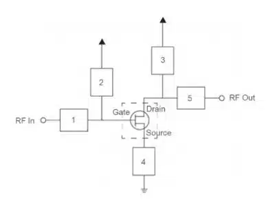
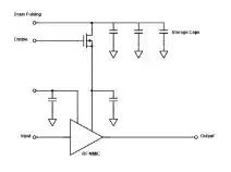
Power amplifiers need several types of capacitors to do their jobs. Here are the main circuit locations (Figure 1) where you’ll find capacitors supporting amplifiers.

Figure 1. Example of the five key circuit locations where capacitors support power amplification

Input/Output Matching and Coupling

Matching ensures that the input and output impedance of an amplifier aligns with the rest of the circuit. In LC matching, inductors (L) and capacitors (C) form networks that facilitate impedance matching between different parts of a circuit to maximize power transfer and minimize echoes in radio frequency (RF) applications.

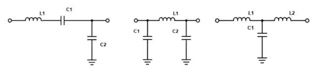
Depending on your application requirements, LC matching networks can be configured a few different ways (Figure 2) to accommodate various operating frequencies and impedance levels:

  • L-Network: Includes an inductor and a capacitor in series or in parallel, depending on whether the impedance needs to be stepped up or down. L-networks are most effective in narrow frequency bands as they don’t allow for much adjustment.
  • Pi-Networks: Form the Greek letter “Pi” with two capacitors and one inductor. They’re designed to transform a low source impedance to a high load impedance or vice versa, so they’re particularly useful in power amplifiers and RF amplifiers.
  • T-Network: Includes two inductors and one capacitor (or two capacitors and one inductor) to form a T-shaped configuration. With greater versatility, T-networks can manage a wider range of impedance values compared to L-networks.
Figure 2. Bandpass L network (left), Pi network (middle) and lowpass T network (right)

While many amplifier monolithic microwave integrated circuits (MMICs) come equipped with matching capabilities, these networks of discrete and distributed elements support finer performance optimizations.

Coupling Capacitors

Coupling describes the linking between different stages of a circuit to ensure effective signal transfer and strong system performance. In radar systems, the way components are coupled can significantly impact signal integrity and power efficiency. With coupling capacitors in series, AC coupling (i.e., DC blocking) connects circuit stages such that only AC signals, like RF or microwave signals, pass from one stage to the next. By extension, this removes any DC offset and protects components by allowing chips with different common mode voltages to interface with each other. Amplifier MMICs can also come with their own coupling, but circuit designers are largely responsible for coupling in high-performance systems.

DC Blocking Capacitors – Bias Networks

Biasing using DC blocking capacitors ensures that the right amount of DC voltage and current goes to an active device (e.g., field-effect transistor (FET)) to keep it operating in an optimal region.

An active device can also connect to a gate, drain, or source bias network. Gate bias networks control voltage at the gate terminal of an FET, relative to its source, to act as a switch in digital applications or a set point for analog applications. Drain bias networks set and control voltage at the drain terminal of an FET, which influences the output characteristics. Source bias networks adjust voltage and current at the source terminal for added stability. Bias networks are critical for setting the quiescent current to optimize amplifier performance metrics like linearity and efficiency.

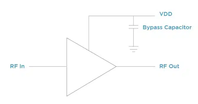
Bypass capacitors and storage capacitors connect to bias networks and contribute to the stability and efficiency of the amplifier circuit. Bypass capacitors act as lowpass filters, allowing DC signal through while removing low- and high-frequency RF noise and interference that could negatively impact the amplifier. Larger capacitance is helpful for low-frequency filtering and smaller capacitance is best suited for higher-frequency RF signals.

Figure 3. Example of a bypass capacitor that provides an efficient path to ground for RF energy

Large charge storage capacitors can maintain power levels during pulsed operation. Aluminum electrolytic capacitors, for example, make great storage capacitors because of their high capacitance density. They’re often found in or near the T/R module and the pulse driver circuitry in a radar system.

Figure 4. Example of power amplification circuit with storage capacitors

From signal conditioning to stability and noise reduction, capacitors support a variety of critical functions in power amplification within radar systems. As these systems grow more and more complex, component-level decisions have a more significant impact on performance. 

Related

Source: Knowles Precision Devices

Recent Posts

Common Mistakes in Flyback Transformer Specs

15.8.2025
8

High Voltage MLCCs Meeting the Growing Demand for Efficiency in Power Conversion

12.8.2025
55

Radiation Tolerance of Tantalum and Ceramic Capacitors

8.8.2025
61

TDK Releases Compact Polypropylene Film Capacitors for Resonant Topologies

7.8.2025
31

Percolation Phenomenon and Reliability of Molded Power Inductors in DC/DC converters

6.8.2025
36

Root Causes and Effects of DC Bias and AC in Ceramic Capacitors

6.8.2025
49

Knowles Unveils High-Performance Safety-Certified MLCC Capacitors

6.8.2025
40

How to Calculate the Output Capacitor for a Switching Power Supply

6.8.2025
46

Evaluation and Modeling of Supercapacitors for Reliability of Lifetime Predictions

4.8.2025
33

Researchers Presents High-Performance Carbon-Based Supercapacitors

1.8.2025
28

Upcoming Events

Aug 27
17:00 - 18:00 CEST

Capacitor Assemblies for High-Power Circuit Designs

Sep 3
15:30 - 17:30 CEST

How to Choose Your Magnetic Supplier

Sep 22
September 22 @ 13:00 - September 25 @ 15:15 EDT

Pre Cap Visual Inspection per Mil-Std-883 (TM 2017)

Sep 30
September 30 @ 12:00 - October 2 @ 14:00 EDT

MIL-Std-883 TM 2010

Oct 17
12:00 - 14:00 EDT

External Visual Inspection per MIL-STD-883 TM 2009

View Calendar

Popular Posts

  • Buck Converter Design and Calculation

    0 shares
    Share 0 Tweet 0
  • Boost Converter Design and Calculation

    0 shares
    Share 0 Tweet 0
  • Flyback Converter Design and Calculation

    0 shares
    Share 0 Tweet 0
  • LLC Resonant Converter Design and Calculation

    0 shares
    Share 0 Tweet 0
  • What is a Dielectric Constant and DF of Plastic Materials?

    4 shares
    Share 4 Tweet 0
  • Ripple Current and its Effects on the Performance of Capacitors

    3 shares
    Share 3 Tweet 0
  • Dual Active Bridge (DAB) Topology Explained

    0 shares
    Share 0 Tweet 0
  • How to Design an Inductor

    0 shares
    Share 0 Tweet 0
  • MLCC Case Sizes Standards Explained

    0 shares
    Share 0 Tweet 0
  • MLCC and Ceramic Capacitors

    0 shares
    Share 0 Tweet 0

Newsletter Subscription


Passive Components Blog

© EPCI - Leading Passive Components Educational and Information Site

  • Home
  • Privacy Policy
  • EPCI Membership & Advertisement
  • About

No Result
View All Result
  • Home
  • Knowledge Blog
  • Premium Suppliers

© EPCI - Leading Passive Components Educational and Information Site

This website uses cookies. By continuing to use this website you are giving consent to cookies being used. Visit our Privacy and Cookie Policy.
Go to mobile version