Passive Components Blog
No Result
View All Result
  • Home
  • NewsFilter
    • All
    • Aerospace & Defence
    • Antenna
    • Applications
    • Automotive
    • Capacitors
    • Circuit Protection Devices
    • electro-mechanical news
    • Filters
    • Fuses
    • Inductors
    • Industrial
    • Integrated Passives
    • inter-connect news
    • Market & Supply Chain
    • Market Insights
    • Medical
    • Modelling and Simulation
    • New Materials & Supply
    • New Technologies
    • Non-linear Passives
    • Oscillators
    • Passive Sensors News
    • Resistors
    • RF & Microwave
    • Telecommunication
    • Weekly Digest

    Samsung Electro-Mechanics Releases High-Capacitance MLCCs for AI Server Applications

    Samsung Electro-Mechanics Releases 165C Automotive 0806 Size Power Inductors

    Coupled Inductors Circuit Model and Examples of its Applications

    Würth Elektronik Introduces LTspice Models for ESD Products

    Capacitor Ripple Current Testing: A Design Consideration

    TDK Releases 0201 High-Frequency Smallest Inductors

    Coilcraft Extends Air Core RF Inductors

    Bourns Releases Automotive 1W Flyback Transformer

    Wk 20 Electronics Supply Chain Digest

    Trending Tags

    • Ripple Current
    • RF
    • Leakage Current
    • Tantalum vs Ceramic
    • Snubber
    • Low ESR
    • Feedthrough
    • Derating
    • Dielectric Constant
    • New Products
    • Market Reports
  • VideoFilter
    • All
    • Antenna videos
    • Capacitor videos
    • Circuit Protection Video
    • Filter videos
    • Fuse videos
    • Inductor videos
    • Inter-Connect Video
    • Non-linear passives videos
    • Oscillator videos
    • Passive sensors videos
    • Resistor videos

    Coupled Inductors Circuit Model and Examples of its Applications

    Inductor Resonances and its Impact to EMI

    Highly Reliable Flex Rigid PCBs, Würth Elektronik Webinar

    Causes of Oscillations in Flyback Converters

    How to design a 60W Flyback Transformer

    Modeling and Simulation of Leakage Inductance

    Power Inductor Considerations for AI High Power Computing – Vishay Video

    Coupled Inductors in Multiphase Boost Converters

    VPG Demonstrates Precision Resistor in Cryogenic Conditions

    Trending Tags

    • Capacitors explained
    • Inductors explained
    • Resistors explained
    • Filters explained
    • Application Video Guidelines
    • EMC
    • New Products
    • Ripple Current
    • Simulation
    • Tantalum vs Ceramic
  • Knowledge Blog
  • Suppliers
    • Who is Who
  • Events
No Result
View All Result
Passive Components Blog
No Result
View All Result

Capacitor Energy Content and Force

2.5.2025
Reading Time: 5 mins read
A A

The article describes capacitor energy content, what energy can be stored and delivered by the capacitor and what forces present inside a capacitor.

Capacitor Energy Content

The energy stored in a capacitor can be described by equation:
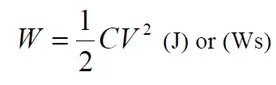
RelatedPosts

Capacitor Charging Losses Explained

Supercapacitor Balancing Methods Comparison

Failure Analysis of Capacitors and Inductors

……………[1]

Force action

from electromagnetic fields

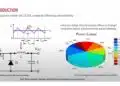
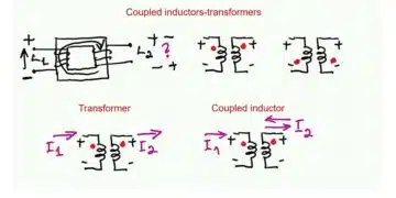
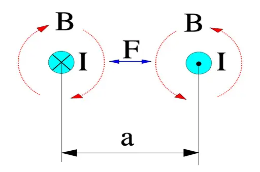
Parallel current carrying conductors are surrounded by magnetic fields exerting forces on each other. If currents flow in the same direction the fields (and the conductors) attract each other. If the current flows in opposite directions they are repelling each other.

Figure 1. Magnetic force action, F, between conductors with a current flow, I. B = magnetic flux density.

If

  • the conductor length l is expressed in m,
  • the current I is expressed in A and
  • the distance a is expressed in m,

the force per meter between the conductors will be
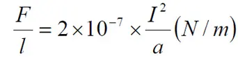
………………………[2]

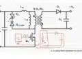
According to the basic charge formula Q = C x V (As). If this expression is derived we obtain dQ/dt = I = C x dV/dt (A). Pulse loads are not unusual, especially in conditions with high voltage gradients, and thus high charging currents also occur which might cause appreciable magnetic fields between close lead patterns, for example.

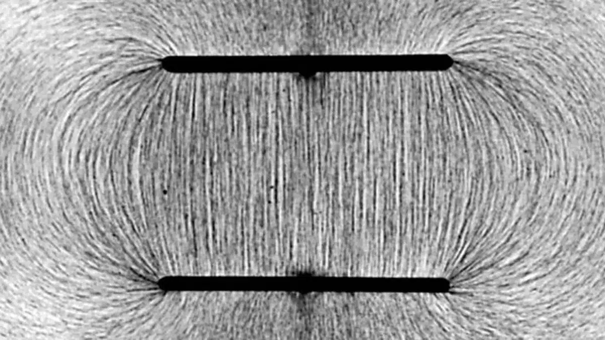
Force action in electrostatic fields

Capacitors are typical examples of applications where electrostatic fields are applied. These fields can generate significant mechanical forces­. If we know the electrode distance d (m) it’s easy to determine the electric field strength E (V/m). Then we can outline the force per unit area, i.e. the pressure that the electrodes exert on the dielectric.
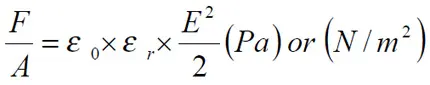
This image has an empty alt attribute; its file name is EQ-C1_22.jpg

……………………………….. [3]

Example. Suppose we have an oil impregnated paper capacitor with r = 5 and the dielectric = 15 m (0.6 mils) which is loaded with 250VAC. Then the instantaneous maximum pressure will be
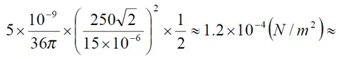
This image has an empty alt attribute; its file name is EQ-C1_22b.jpg

0.1 kp/cm2 !

If we instead calculate on a 35 V solid tantalum capacitor with a typical and approximate dielectric thickness of 0.2 mm (0.008 mils) the formula gives at 30 V DC a pressure of
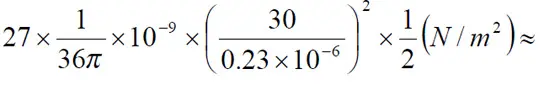
This image has an empty alt attribute; its file name is EQ-C1_22c.jpg

2 N/mm2 !

It is difficult to determine how much the dielectric is influenced by such forces, especially when the electrodes have such complex configurations. Electrostatic action of such forces here is of vital importance.

Electrostatic Force Potential Impact

We learned in the article about the energy stored in the capacitor, but what is also important and demonstrated is that there is enormous mechanical pressure between the electrodes once voltage is applied.

This can be considered in failure analyses if we have a solid, sharp impurity within the capacitor dielectric – it may degrade the insulator not only by inducing electrical conductivity/increasing leakage current, but also causing a mechanical damage to the dielectric due to the high electrostatic pressure between the electrodes. Hard and sharp micro-crystals in amorphous dielectric could be an example of such defects.

Related

Recent Posts

Samsung Electro-Mechanics Releases High-Capacitance MLCCs for AI Server Applications

21.5.2025
26

Coupled Inductors Circuit Model and Examples of its Applications

21.5.2025
18

Würth Elektronik Introduces LTspice Models for ESD Products

21.5.2025
19

Littelfuse Gate Driver Integrates Diode and Current Limit Resistor in Compact IC

21.5.2025
7

Capacitor Ripple Current Testing: A Design Consideration

21.5.2025
31

Inductor Resonances and its Impact to EMI

16.5.2025
48

Developing Low Inductance Film Capacitor using Bode 100 Analyzer

15.5.2025
43

Causes of Oscillations in Flyback Converters

15.5.2025
26

YAGEO Extends Rectangular Aluminum Electrolytic Capacitor Family

15.5.2025
53

Dr. Tomas Zednicek Vision for Europe 2025 Passive Electronics Market

14.5.2025
48

Upcoming Events

May 28
16:00 - 17:00 CEST

Power Over Data Line

View Calendar

Popular Posts

  • Buck Converter Design and Calculation

    0 shares
    Share 0 Tweet 0
  • Boost Converter Design and Calculation

    0 shares
    Share 0 Tweet 0
  • Flyback Converter Design and Calculation

    0 shares
    Share 0 Tweet 0
  • What is a Dielectric Constant and DF of Plastic Materials?

    4 shares
    Share 4 Tweet 0
  • How to Design an Inductor

    0 shares
    Share 0 Tweet 0
  • LLC Resonant Converter Design and Calculation

    0 shares
    Share 0 Tweet 0
  • Capacitor Ripple Current Testing: A Design Consideration

    0 shares
    Share 0 Tweet 0
  • Inductor Resonances and its Impact to EMI

    0 shares
    Share 0 Tweet 0
  • Capacitor Losses (ESR, IMP, DF, Q), Series or Parallel Eq. Circuit ?

    0 shares
    Share 0 Tweet 0
  • Ripple Current and its Effects on the Performance of Capacitors

    3 shares
    Share 3 Tweet 0

Newsletter Subscription


Passive Components Blog

© EPCI - Leading Passive Components Educational and Information Site

  • Home
  • Privacy Policy
  • EPCI Membership & Advertisement
  • About

No Result
View All Result
  • Home
  • Knowledge Blog
  • Premium Suppliers

© EPCI - Leading Passive Components Educational and Information Site

This website uses cookies. By continuing to use this website you are giving consent to cookies being used. Visit our Privacy and Cookie Policy.
Go to mobile version