


Source: TDK technical library article
High-power loads are a major stress factor when fuses and components are switched on, as they cause very high currents to flow. To avoid this, TDK offers ceramic EPCOS inrush current limiters (ICLs), based on NTC and PTC thermistors – a strong duo when used in combination.
When high power loads such as power supplies, frequency converters or on-board chargers are powered up, currents that can be many times the rated current occur for a short period. This can result in undesirable effects, such as the tripping of fuses, or even damage to the system. Two types of load in particular are responsible for high inrush currents: On the one hand, these are inductive loads such as motors and transformers, which require very high currents in order to create the magnetic fields. The other group are high-capacitance capacitors in DC links, which cause very high charging currents at the moment of connection, which represents a considerable stress factor for the capacitors themselves, as well as for the rectifiers. Figure 1 shows the current flow with and without inrush current limiters (ICLs).

Figure 1: Current flow in a rectifier without inrush current limitation (red) and with inrush current limitation (green).
The simplest way is for inrush currents to be limited using low-ohmic power resistors. This does however have the disadvantage that in normal mode a power loss occurs at these resistors that should not to be ignored. A considerably better solution is the use of thermistors in their function as ICLs. NTC or PTC thermistors, which exhibit different thermal characteristics and thus offer different possibilities for use, are used for this purpose. One way of exploiting all the benefits of these components is to use them in combination. First let us look at the NTC thermistors:
Elegant solution with NTC thermistors
One very elegant solution for limiting high input-side inrush currents is the use of EPCOS NTC thermistors. Functional principle: These ceramic components are temperature-dependent resistors whose resistance drops as the temperature rises. At room temperature (25 °C) they exhibit a specific resistance value (R25) which limits the inrush current. When current continues to flow through the component it heats up and the resistance falls to very low values which, depending on the type, can be significantly below one ohm. The losses at the rated current are correspondingly low. Figure 2 shows typical resistor characteristic curves of various NTC ICLs relative to temperature.


Figure 2: Typical characteristic curves of EPCOS NTC ICLs. Right: NTC inrush current limiter with a starting resistance R25 of 10 Ω.
Selection criteria for NTC ICLs
The two most important criteria for determining the suitable NTC thermistor are the initial resistance (R25) and the maximum current. First, the required R25 is determined. It must be selected high enough so that, by connecting it in series with the load, it limits the current to a value that does not yet cause the fuse to trip, and so that no damage occurs to components of the load such as rectifiers.
The second criterion is Imax, which is determined by the power rating of the load. The important thing here is the derating of the NTC thermistor. A typical example of this is shown in Figure 3.

Figure 3: Typical derating characteristic of NTC ICLs.
TDK offers a wide range of NTC thermistors with an R25 of between 0.5 Ω and 33 Ω and permissible currents of 1.3 A to 30 A.
When using the ICLs, a cooling time of about 90 s depending on type should be ensured, which can be problematic in the case of loads that are frequently switched on and off at short intervals, as a warmed-up NTC thermistor is very low ohmic and thus offers almost no current limiting. A remedy is provided here by the bypassing of the NTC thermistors using a relay or a thyristor. This can take place just a few seconds after switching on, as most loads are then already being operated with the rated current. Thanks to the bypass, there is no warming of the NTC thermistor. Figure 4 shows a time-controlled bypass circuit for ICLs.

Figure 4: Time-controlled bypass circuit for ICLs.
The response time of the bypass circuit is determined by the time constants of R1 and C1 as well as the value of the Zener diode. In the example circuit the relay responds after about 3 or 4 seconds – depending on the tolerances of the components. On the relay used (24 V DC, 8 A AC) the holding voltage of the coil is around 0.5 UN. Due to the charging current of C2 the relay responds and is operated at half the rated voltage after C2 has been charged, which halves the current requirement. Particularly if the loads have high rated currents, the power demand of this circuit is less than the losses caused by the continuous current flow through the NTC thermistor.
Reliable capacitor charging by PTC thermistors
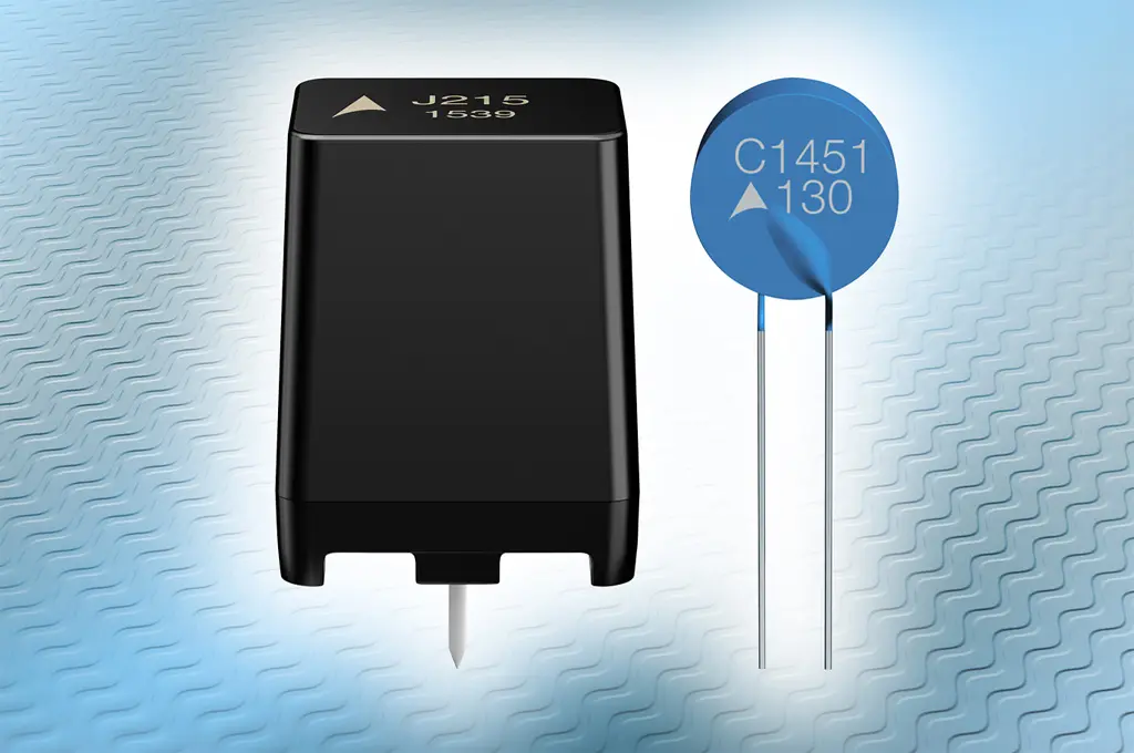
High-capacitance capacitors and capacitor banks in DC link circuits represent a short circuit at the moment of switching on. In order to achieve reliable current limitation here, PTC thermistors should be used instead of fixed resistors. The high current flow causes these components to heat up and – contrary to NTC thermistors – become high-ohmic, which makes them intrinsically safe. This behavior offers the advantage that, in the case of a short-circuit in the DC link, the current is limited to harmless values, something that fixed resistors cannot offer. Figure 5 shows the DC link circuit of a 3-phase system with PTC thermistor which is used, for example, in frequency converters.


Figure 5: DC link circuit with charging current limitation by PTC thermistor. Right: PTC thermistors in housed and standard disk designs.
For DC link circuits, TDK offers a series of special PTC thermistors that are designed for voltages of between 260 V DC and 560 V DC, offering resistances between 22 Ω and 1100 Ω at 25 °C and, depending on their type, have approvals compliant with UL, IECQ and VDE, as well as being qualified in accordance with AEC-Q200.
Particularly in the case of larger banks of capacitors, care should be taken that the maximum thermal capacitance and maximum permissible temperature of the PTC thermistors are not exceeded. The necessary thermal capacitance can be achieved by connecting the PTC ICLs in parallel. The required minimum number of components is calculated as follows:

Where:
n Number of PTC elements required
k Factor is dependent on the power supply (k = 1 for DC; k = 0.96 for 3-phase rectifier; k = 0.76 for half-wave rectifier)
C Capacitance of the DC link capacitor in F
V Maximum charging voltage of the capacitor in V
Cth Thermal capacitance of the PTC thermistor
TRef Reference temperature of the PTC thermistors used
TAmax Maximum ambient temperature
In normal operation the PTC ICL, or several PTC ICLs connected in parallel, must be bypassed after charging the DC link capacitors in order not to produce any power losses. There must be no bypass, however, if there is a short circuit in the DC link – caused perhaps by damaged capacitors. The most significant parameter for a bypass circuit therefore is the DC link voltage. If, after charging, it reaches the setpoint, there is no fault; if, on the other hand, it remains at a very low value for a longer period, there is a short circuit. This enables a comparator circuit to be implemented with little effort, which bypasses the PTC thermistor only after charging of the DC link (Figure 6).

Figure 6: Voltage-controlled bypass for PTC thermistors.
Notes on the function: The inverting input of the comparator is controlled via the Zener diode ZPD3.9. As long as a voltage of less than 3.9 V is applied to the non-inverting input, a voltage of almost 0 V appears at the output and T1 blocks the relay. Only when a voltage of more than 3.9 V is applied via the voltage dividers R1/R2 to R2 does the comparator at the output trip to positive potential and T1 switches the relay, causing the PTC thermistor to be bypassed. The voltage dividers R1/R2 should be dimensioned in such a way that the relay switches at about 80 percent of the rated DC link voltage. As DC link voltages can be several hundreds of volts, high-impedance types must be used for R1 and R2. Example: At a rated DC link voltage of 500 V DC the value of 80 percent is reached at 400 V DC. At this point, the value for R1 is about 990 kΩ and for R2 it is about 10 kΩ. The varistor and the Zener diode ZPD12 serve to protect the non-inverting input of the comparator against overvoltages.
Combining the advantages
Especially in the case of high-power loads that have high DC link capacitances, such as those in industrial power supplies and converters, it is advisable to combine the advantages and functions of NTC and PTC inrush current limiters.
It is sensible therefore to use the voltage-controlled ON time described here also for bypassing the NTC thermistor on the power input side. For this purpose, a relay with two changeover contacts is required in the circuit shown in Figure 6. Figure 7 then shows the complete circuit, in which the NTC and PTC thermistors are switched simultaneously. In addition, an LED has been integrated which indicates that the jumper has not yet been applied.

Figure 7: Voltage-controlled combination of NTC and PTC inrush current limiters.
The advantages of such combined inrush current limitations are the protection of components, the avoidance of unintentional tripping of supply-side or device-internal fuses, and reliable current limiting in the event of short-circuits in the DC link.


