Passive Components Blog
No Result
View All Result
  • Home
  • NewsFilter
    • All
    • Aerospace & Defence
    • Antenna
    • Applications
    • Automotive
    • Capacitors
    • Circuit Protection Devices
    • electro-mechanical news
    • Filters
    • Fuses
    • Inductors
    • Industrial
    • Integrated Passives
    • inter-connect news
    • Market & Supply Chain
    • Market Insights
    • Medical
    • Modelling and Simulation
    • New Materials & Supply
    • New Technologies
    • Non-linear Passives
    • Oscillators
    • Passive Sensors News
    • Resistors
    • RF & Microwave
    • Telecommunication
    • Weekly Digest

    ECIA Industry Pulse Index Cools After Five-Year High

    YAGEO Extends Automotive CAN and CAN-FD Common-Mode Chokes

    Würth Elektronik Updates REDEXPERT DC‑DC Converter Designer

    Stackpole Unveils High-Temperature Automotive Thick Film Chip Resistors for Harsh Environments

    Molex Presents MiniMix Hybrid Power and Signal Connectors for Compact Humanoid Joints

    Bourns Releases Custom SiC AFE/PFC Power Inductor for High‑Voltage Designs

    Littelfuse Releases Toggle Safety Covers for Reliable Control Panels

    Bourns Expanded Blend‑Balance Guitar Potentiometers Resistance Range

    TDK Extends Vibration‑Resistant Axial Aluminum Capacitors for Compact DC‑links

    Trending Tags

    • Ripple Current
    • RF
    • Leakage Current
    • Tantalum vs Ceramic
    • Snubber
    • Low ESR
    • Feedthrough
    • Derating
    • Dielectric Constant
    • New Products
    • Market Reports
  • VideoFilter
    • All
    • Antenna videos
    • Capacitor videos
    • Circuit Protection Video
    • Filter videos
    • Fuse videos
    • Inductor videos
    • Inter-Connect Video
    • Non-linear passives videos
    • Oscillator videos
    • Passive sensors videos
    • Resistor videos

    Current Sense Transformers: Ferrite vs Nanocrystalline Cores for Accurate Current Measurement

    EMC Design Fundamentals: Safe Use of Varistors and Common Mode Chokes in Mains and Data-Line Filters

    Ferrite versus Nanocrystalline Power Inductor Cores: Turns, Gap and Size

    KYOCERA AVX Presents Antenna Integrator Studio Tutorial for Antenna Placement and RF Design

    Power Design Simulation Tools for Faster Inductor Selection and Loss Optimization

    EMC‑Compliant PCB and Connector Design Guidelines

    Why Isolated DC/DC Power Supplies Fail Late, Würth Elektronik Podcast

    Designing 800 V DC EMC Filters: Calculation, Simulation and Measurement

    Current Sense Transformer Datasheet and Design‑in Guide

    Trending Tags

    • Capacitors explained
    • Inductors explained
    • Resistors explained
    • Filters explained
    • Application Video Guidelines
    • EMC
    • New Products
    • Ripple Current
    • Simulation
    • Tantalum vs Ceramic
  • Knowledge Blog
  • Dossiers
    • AI Hardware Dossier
    • Power Converter Dossier
    • Automotive Dossier
    • Capacitor Dossier
    • Resistor Dossier
    • Inductor Dossier
    • Circuit Protection Dossier
  • Suppliers
    • Who is Who
  • PCNS
    • PCNS 2025
    • PCNS 2023
    • PCNS 2021
    • PCNS 2019
    • PCNS 2017
  • Events
  • Home
  • NewsFilter
    • All
    • Aerospace & Defence
    • Antenna
    • Applications
    • Automotive
    • Capacitors
    • Circuit Protection Devices
    • electro-mechanical news
    • Filters
    • Fuses
    • Inductors
    • Industrial
    • Integrated Passives
    • inter-connect news
    • Market & Supply Chain
    • Market Insights
    • Medical
    • Modelling and Simulation
    • New Materials & Supply
    • New Technologies
    • Non-linear Passives
    • Oscillators
    • Passive Sensors News
    • Resistors
    • RF & Microwave
    • Telecommunication
    • Weekly Digest

    ECIA Industry Pulse Index Cools After Five-Year High

    YAGEO Extends Automotive CAN and CAN-FD Common-Mode Chokes

    Würth Elektronik Updates REDEXPERT DC‑DC Converter Designer

    Stackpole Unveils High-Temperature Automotive Thick Film Chip Resistors for Harsh Environments

    Molex Presents MiniMix Hybrid Power and Signal Connectors for Compact Humanoid Joints

    Bourns Releases Custom SiC AFE/PFC Power Inductor for High‑Voltage Designs

    Littelfuse Releases Toggle Safety Covers for Reliable Control Panels

    Bourns Expanded Blend‑Balance Guitar Potentiometers Resistance Range

    TDK Extends Vibration‑Resistant Axial Aluminum Capacitors for Compact DC‑links

    Trending Tags

    • Ripple Current
    • RF
    • Leakage Current
    • Tantalum vs Ceramic
    • Snubber
    • Low ESR
    • Feedthrough
    • Derating
    • Dielectric Constant
    • New Products
    • Market Reports
  • VideoFilter
    • All
    • Antenna videos
    • Capacitor videos
    • Circuit Protection Video
    • Filter videos
    • Fuse videos
    • Inductor videos
    • Inter-Connect Video
    • Non-linear passives videos
    • Oscillator videos
    • Passive sensors videos
    • Resistor videos

    Current Sense Transformers: Ferrite vs Nanocrystalline Cores for Accurate Current Measurement

    EMC Design Fundamentals: Safe Use of Varistors and Common Mode Chokes in Mains and Data-Line Filters

    Ferrite versus Nanocrystalline Power Inductor Cores: Turns, Gap and Size

    KYOCERA AVX Presents Antenna Integrator Studio Tutorial for Antenna Placement and RF Design

    Power Design Simulation Tools for Faster Inductor Selection and Loss Optimization

    EMC‑Compliant PCB and Connector Design Guidelines

    Why Isolated DC/DC Power Supplies Fail Late, Würth Elektronik Podcast

    Designing 800 V DC EMC Filters: Calculation, Simulation and Measurement

    Current Sense Transformer Datasheet and Design‑in Guide

    Trending Tags

    • Capacitors explained
    • Inductors explained
    • Resistors explained
    • Filters explained
    • Application Video Guidelines
    • EMC
    • New Products
    • Ripple Current
    • Simulation
    • Tantalum vs Ceramic
  • Knowledge Blog
  • Dossiers
    • AI Hardware Dossier
    • Power Converter Dossier
    • Automotive Dossier
    • Capacitor Dossier
    • Resistor Dossier
    • Inductor Dossier
    • Circuit Protection Dossier
  • Suppliers
    • Who is Who
  • PCNS
    • PCNS 2025
    • PCNS 2023
    • PCNS 2021
    • PCNS 2019
    • PCNS 2017
  • Events
No Result
View All Result
Passive Components Blog
No Result
View All Result

Bourns Unveils High Volt GDT for High‑Energy Surge Protection

23.2.2026
Reading Time: 8 mins read
A A

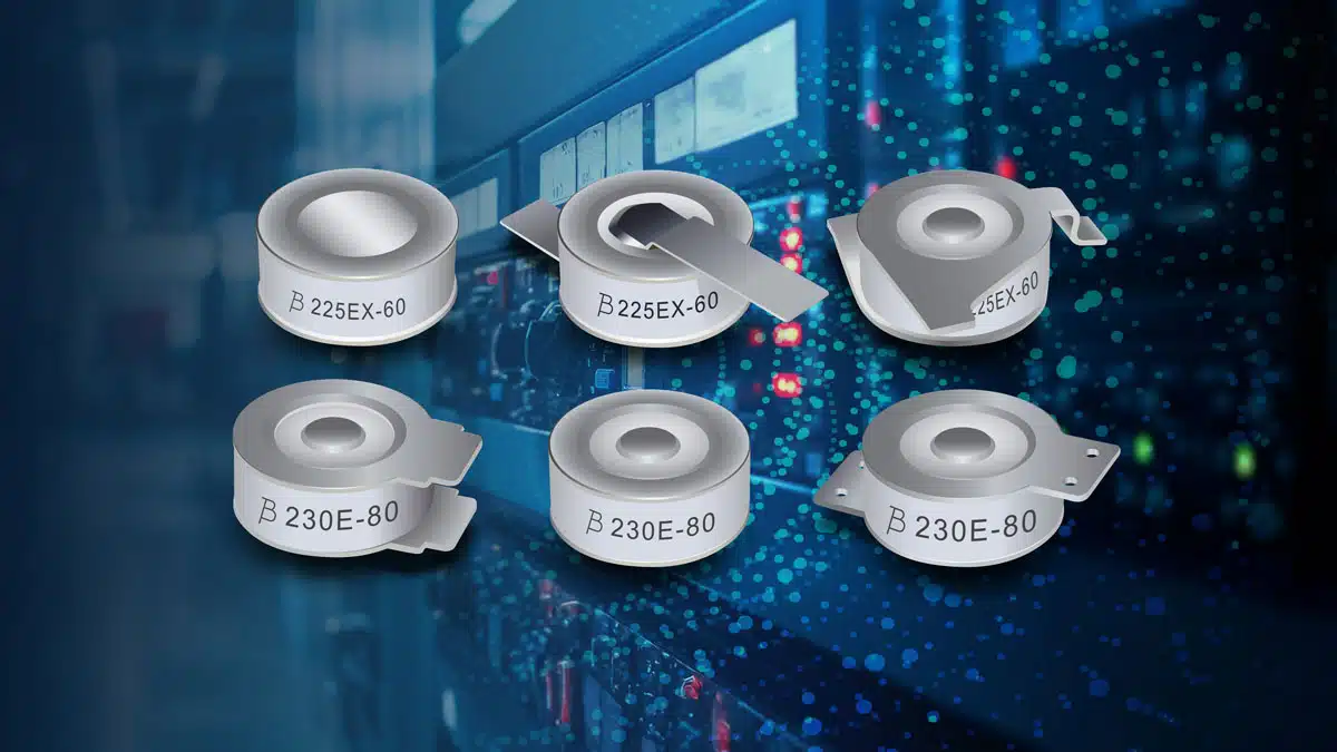
Bourns has introduced the GDT225HE Series, a new family of high voltage, high energy gas discharge tubes (GDTs) designed for demanding surge protection in power and energy systems.

These GDT circuit protection components target lightning‑prone, high energy environments where conventional protection elements alone may not provide sufficient robustness. The series combines high surge current ratings with a broad breakdown voltage range in a compact form factor suitable for high density designs.

RelatedPosts

Bourns Releases Custom SiC AFE/PFC Power Inductor for High‑Voltage Designs

Bourns Expanded Blend‑Balance Guitar Potentiometers Resistance Range

Bourns Introduces Automotive Wide Terminal Metal Foil Current Sense Resistors for High‑Reliability Designs

Key features and benefits

The GDT225HE Series is a UL Recognized family of high voltage, high energy gas discharge tubes intended for primary surge protection in power and infrastructure applications. According to the manufacturer, the series is tested per ITU‑T K.12 methods, which is widely used as a reference for telecom and surge protective devices.

Key electrical features include:

  • DC breakdown voltage (DCBV) range from 1000 V to 2000 V (nominal), allowing coordinated protection on medium to high voltage lines according to the manufacturer datasheet.
  • DC breakdown voltage tolerance of ±20%, typical for GDT technology and relevant for coordination with downstream MOVs or TVS components.
  • Maximum impulse breakdown voltage specified at 6 kV (1.2/50 µs, two operations) according to the featured product bulletin.
  • Impulse discharge current capability on an 8/20 µs surge waveform with:
    • Nominal impulse discharge current In of 40 kA.
    • Maximum impulse discharge current Imax of 60 kA.
  • High energy handling on a 10/350 µs surge waveform with a maximum impulse discharge current rating of 12.5 kA for the GDT225HE‑100 version.

These ratings position the GDT225HE as a primary surge element for systems exposed to high lightning currents or switching surges.

From a practical design perspective, the series offers:

  • Compact, space‑saving construction suitable for high density and space‑restricted PCB layouts.
  • A variety of lead shapes to fit different mechanical configurations and assembly preferences.
  • Low capacitance and low insertion loss, helping to minimize impact on signal integrity and power system performance.
  • Fast response time (specified breakdown time < 100 ns for 100–2000 V/s ramp rates), supporting rapid clamp of fast transients.
  • Stable performance throughout life, with insulation resistance limits after life ratings still above 100 MΩ according to the manufacturer.
  • RoHS compliance as per the referenced directive.

For designers, the combination of high surge capability, low parasitics and compact size simplifies protection design in high energy environments where board space and long‑term reliability are both critical.

Typical applications

The GDT225HE Series is targeted at surge protection in high energy systems where lightning or switching surges are expected on power lines and DC buses. Typical application domains called out by the manufacturer include:

  • Surge protective devices (SPDs) used as primary or intermediate protection stages in power distribution and equipment‑level surge protection.
  • Power systems, including AC distribution panels, power conversion equipment and upstream protection at equipment inputs.
  • Industrial equipment with long cable runs, exposed outdoor interfaces, or high power switching elements.
  • Renewable energy systems such as solar and wind installations, where long DC strings and outdoor exposure increase lightning susceptibility.
  • Energy storage systems, including battery energy storage, where high energy surge events may couple into DC busbars and system interfaces.

In many of these applications, the GDT225HE would be used in combination with other protection components (for example, a suitable MOV in series as noted by the manufacturer) to achieve a coordinated protection scheme that can both withstand high surge currents and limit residual voltage to safe levels for downstream electronics.

Technical highlights

The featured product bulletin provides a key parameter overview for the GDT225HE‑100 part number, which is representative of the series:

  • Part number: GDT225HE‑100.
  • Nominal DC breakdown voltage: 1000 V.
  • Maximum impulse breakdown voltage: 1800 V.
  • Maximum impulse discharge current (8/20 µs): 60 kA.
  • Nominal impulse discharge current (8/20 µs, 15 operations): 40 kA.
  • Maximum impulse discharge current (10/350 µs, 1 operation): 12.5 kA.
  • Temporary overvoltage (TOV) withstand at 1200 V for 0.2 s as defined by the manufacturer.
  • Maximum follow‑on current at 50/60 Hz: 300 A.
  • Maximum continuous operating voltage (MCOV) at 50/60 Hz: 255 V (when used with a suitable MOV in series as noted in the bulletin).
  • Minimum insulation resistance: 1 GΩ (test voltage 500 V).
  • Breakdown time: < 100 ns at 100–2000 V/s.

Other voltage variants in the family are listed as:

  • GDT225HE‑120 – nominal 1200 V DC breakdown.
  • GDT225HE‑140 – nominal 1400 V DC breakdown.
  • GDT225HE‑160 – nominal 1600 V DC breakdown.
  • GDT225HE‑180 – nominal 1800 V DC breakdown.
  • GDT225HE‑200 – nominal 2000 V DC breakdown.

For these variants, maximum impulse breakdown voltages are given up to 3000 V at 1.2/50 µs according to the manufacturer’s table. Exact surge current capability for each variant should be confirmed against the detailed datasheet, but the series in general is positioned as a high surge current GDT family.

The manufacturer notes that:

  • DC and impulse sparkover values are specified in ionized mode at 25 °C, which is important when comparing to other GDTs or setting protection coordination margins.
  • Impulse sparkover voltage is expressed as a maximum value with a 99% probability that measured values will be within the stated limit.
  • DC sparkover voltage limits after life testing may exceed +20%, but devices are designed to continue providing protection without venting, referencing ITU‑T K.12 Edition 9.0.
  • Surface mount versions (where applicable) are intended to be reflowed according to IPC/JEDEC J‑STD‑020 rev. D.

These details are relevant for long‑term reliability, compliance, and for accurately modeling worst‑case behavior in surge protection design.

Design‑in notes for engineers

When integrating the GDT225HE Series into a surge protection design, engineers should consider the following practical aspects:

  • Coordination with MOVs and downstream protection
    The bulletin notes that certain specifications, such as MCOV, are defined when the GDT is used with a suitable MOV in series. This is typical in AC mains and DC bus protection where the GDT handles the highest energy surge while the MOV clamps the residual voltage. Engineers should select MOV ratings and clamping levels consistent with the chosen GDT breakdown voltage and with the equipment insulation coordination requirements.
  • Selection of breakdown voltage
    The choice between 1000 V, 1200 V, 1400 V, 1600 V, 1800 V or 2000 V versions depends on:
    • System nominal voltage and overvoltage profile.
    • Required insulation coordination and creepage/clearance design.
    • Coordination with other surge protection stages (line‑side SPDs, downstream TVS diodes, etc.).
      Higher breakdown versions can reduce nuisance operation under normal overvoltage, at the cost of higher residual voltages during surge events.
  • Surge rating versus expected threat level
    The 40 kA/60 kA ratings on 8/20 µs waveforms and 12.5 kA on 10/350 µs provide significant headroom for systems where direct or nearby lightning currents are expected. Designers should map these ratings to local SPD class requirements, test classes and installation conditions, paying attention to the number of operations specified in the bulletin (for example, 15 operations at nominal 8/20 µs current).
  • Thermal and mechanical considerations
    Although GDTs dissipate most surge energy in a short pulse, PCB layout should allow adequate thermal spreading and robust solder joints for the lead style selected. Keeping current paths short and minimizing loop inductance will help achieve the intended protection performance.
  • Testing and verification
    Because impulse sparkover voltages are given as maximum values with 99% probability, prototypes should be evaluated under realistic surge and TOV conditions. This includes:
    • Verifying coordination with upstream and downstream SPDs.
    • Confirming that follow‑on current remains within system limits given the specified 300 A maximum follow‑on current rating at 50/60 Hz for the GDT225HE‑100.
    • Checking post‑surge insulation resistance against system safety and leakage requirements.
  • Standards context
    The references to ITU‑T K.12 test methods and to specific notes on life ratings and DC sparkover voltage drift are helpful when positioning the GDT225HE within telecom and power SPD standards. Designers working under IEC or UL frameworks can use these references as a starting point for mapping to the applicable surge test classes and safety requirements.

Overall, the GDT225HE Series gives designers a high energy primary protection element for modern power, renewable and storage systems where high surge currents, high operating voltages and limited board space must be balanced.

Source

The information in this article is based on the official Bourns new product release for the GDT225HE Series high voltage, high energy gas discharge tubes and associated featured product bulletin, combined with general surge protection design practice.


References

  1. Bourns GDT225HE Series – Featured Product Bulletin (New Product Release)
  2. Bourns official website – Gas Discharge Tubes product overview

Related

Recent Posts

YAGEO Extends Automotive CAN and CAN-FD Common-Mode Chokes

10.8.2026
7

Stackpole Unveils High-Temperature Automotive Thick Film Chip Resistors for Harsh Environments

6.8.2026
39

Molex Presents MiniMix Hybrid Power and Signal Connectors for Compact Humanoid Joints

6.8.2026
51

Bourns Releases Custom SiC AFE/PFC Power Inductor for High‑Voltage Designs

6.8.2026
47

Littelfuse Releases Toggle Safety Covers for Reliable Control Panels

6.8.2026
15

TDK Extends Vibration‑Resistant Axial Aluminum Capacitors for Compact DC‑links

4.8.2026
50

YAGEO Releases SMD 0402 Pt Temperature Sensors for Space‑Constrained Designs

3.8.2026
61

Bourns Introduces Automotive Wide Terminal Metal Foil Current Sense Resistors for High‑Reliability Designs

3.8.2026
34

YAGEO Extends Automotive Tantalum Polymer Capacitors for AI and ADAS Controllers

31.7.2026
122

Upcoming Events

Sep 10
11:00 - 12:00 CEST

Equipment models and model strategies for Space Missions

Sep 29
16:00 - 17:00 CEST

Cybersecurity 2026

Nov 24
16:00 - 17:00 CET

Component selection with the WE REDEXPERT® DC-DC Converter Designer Tool

View Calendar

Popular Posts

  • Buck Converter Design and Calculation

    0 shares
    Share 0 Tweet 0
  • Boost Converter Design and Calculation

    0 shares
    Share 0 Tweet 0
  • LLC Resonant Converter Design and Calculation

    0 shares
    Share 0 Tweet 0
  • MLCC and Ceramic Capacitors

    0 shares
    Share 0 Tweet 0
  • Flyback Converter Design and Calculation

    0 shares
    Share 0 Tweet 0
  • MLCCs in the Age of AI: Q2 2026 Market Tightness

    0 shares
    Share 0 Tweet 0
  • YAGEO Announces July 2026 Capacitor Price Increase

    0 shares
    Share 0 Tweet 0
  • Earthing Systems and IEC Classification Explained

    0 shares
    Share 0 Tweet 0
  • Ripple Current and its Effects on the Performance of Capacitors

    3 shares
    Share 3 Tweet 0
  • Dual Active Bridge (DAB) Topology

    0 shares
    Share 0 Tweet 0

Newsletter Subscription


Passive Components Blog

© EPCI - Leading Passive Components Educational and Information Site

  • Home
  • Privacy Policy
  • EPCI Membership & Advertisement
  • About

No Result
View All Result
  • Home
  • Knowledge Blog
  • Dossiers
  • PCNS

© EPCI - Leading Passive Components Educational and Information Site