Passive Components Blog
No Result
View All Result
  • Home
  • NewsFilter
    • All
    • Aerospace & Defence
    • Antenna
    • Applications
    • Automotive
    • Capacitors
    • Circuit Protection Devices
    • electro-mechanical news
    • Filters
    • Fuses
    • Inductors
    • Industrial
    • Integrated Passives
    • inter-connect news
    • Market & Supply Chain
    • Market Insights
    • Medical
    • Modelling and Simulation
    • New Materials & Supply
    • New Technologies
    • Non-linear Passives
    • Oscillators
    • Passive Sensors News
    • Resistors
    • RF & Microwave
    • Telecommunication
    • Weekly Digest

    Smolteks CNF MIM Capacitor Break 1 µF/mm²

    Samsung Electro-Mechanics Releases 0201 X7T 1uF 6.3V MLCC for ADAS Applications

    Murata Announces 0402 Automotive Chip Ferrite Beads for V2X

    2025 Thick and Thin Film Resistor Networks Environment Overview

    Role of High-Q Ceramic Filters to Overcome GNSS Jamming

    Optimization of IoT for GEO NB-NTN Hybrid Connectivity

    TDK Releases Automotive Power-Over-Coax Inductor for Filters

    Advanced Conversion Announces Mass Production of 200C Film Capacitors

    VinaTech Supercapacitors: Enhancing Smart Meter Reliability and Efficiency

    Trending Tags

    • Ripple Current
    • RF
    • Leakage Current
    • Tantalum vs Ceramic
    • Snubber
    • Low ESR
    • Feedthrough
    • Derating
    • Dielectric Constant
    • New Products
    • Market Reports
  • VideoFilter
    • All
    • Antenna videos
    • Capacitor videos
    • Circuit Protection Video
    • Filter videos
    • Fuse videos
    • Inductor videos
    • Inter-Connect Video
    • Non-linear passives videos
    • Oscillator videos
    • Passive sensors videos
    • Resistor videos

    Understanding Switched Capacitor Converters

    Coupled Inductors Circuit Model and Examples of its Applications

    Inductor Resonances and its Impact to EMI

    Highly Reliable Flex Rigid PCBs, Würth Elektronik Webinar

    Causes of Oscillations in Flyback Converters

    How to design a 60W Flyback Transformer

    Modeling and Simulation of Leakage Inductance

    Power Inductor Considerations for AI High Power Computing – Vishay Video

    Coupled Inductors in Multiphase Boost Converters

    Trending Tags

    • Capacitors explained
    • Inductors explained
    • Resistors explained
    • Filters explained
    • Application Video Guidelines
    • EMC
    • New Products
    • Ripple Current
    • Simulation
    • Tantalum vs Ceramic
  • Knowledge Blog
  • Suppliers
    • Who is Who
  • Events
No Result
View All Result
Passive Components Blog
No Result
View All Result

Comparative Evaluation of Wet Testing and Mechanical Testing for Quality Control of Tantalum Powder in Capacitor Production

2.7.2024
Reading Time: 9 mins read
A A

This article written by Dr. Vladimir Azbel, independent consultant on tantalum capacitors, compares conventional wet testing and proposed mechanical testing of anodes to predict quality of tantalum capacitors.

Introduction

    Powder control is a crucial factor in tantalum capacitor production.

    RelatedPosts

    Enhanced Process Control in Tantalum Capacitor Anode Manufacturing Reduces Cost and Improves Reliability

    Enhancing Effectiveness of Tantalum Capacitor Anode Control

    Risk of Tantalum Capacitor Anode Overheating: Modeling and Practical Solutions

    This paper discusses two methods for assessing the quality of tantalum powder in capacitor production: wet testing and mechanical testing. While wet testing is a reliable method for correlating powder characteristics with capacitance and leakage current, it is limited in the early stages, of evaluation, particularly for leakage currents. Mechanical testing, with significant advantages over wet testing, offers early defect detection and comprehensive quality assessment of the powder. Introducing mechanical testing is recommended to enhance reliability.

    Wet vs Mechanical Anode Reliability Assessment 

    Wet Test Methodology for Evaluating Tantalum Capacitor Anodes

    Of the current powder inspection methods available to capacitor manufacturers, wet testing is currently the most reliable method. The wet test is a direct correlation between powder characteristics and anode capacitance and leakage current.

    The setup (see Fig. 1) and procedures for testing capacitance and leakage current are well standardized.

    Figure 1. Wet testing the anode in a tantalum capacitor

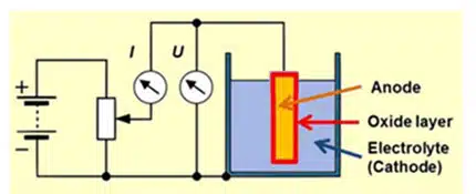
    Fig. 1 illustrates the setup for wet testing the anode in a tantalum capacitor, showing how the anode is immersed in the electrolyte and connected to the measurement instruments.

    Wet Test Methodology Involves Several Steps:

    1. Sample Preparation: The anode is placed in the electrolyte (see Fig. 1).
    2. Voltage Application: The rating voltage of the capacitor or slightly higher is applied to the anode.
    3. Measurements: Leakage current and capacitance are measured.
    4. Result Analysis: The obtained data are compared with the technical specifications set by the capacitor manufacturer.

    Mechanical Test Methodology

    Mechanical Test Methodology: Stress-Strain Curve

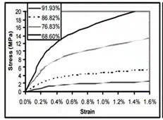
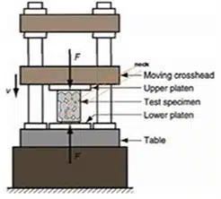
    Stress-strain curves, demonstrating high sensitivity to changes in the porous structure, are used to assess the material structure obtained by powder metallurgy methods (see Fig. 2). The setup of the testing machine for obtaining stress-strain curves is shown in Fig. 3.

    Figure 2. Stress-strain curves of tantalum with different porosities
    Figure 3. Schematic of the testing machine setup.

    To Obtain the Stress-Strain Curve of a Powder Product, the Following Steps Are Necessary:

    1. Sample Preparation: A pellet is pressed from tantalum powder and subjected to sintering.
    2. Tensile or Compression Testing Equipment: (see Fig. 3).
    3. Testing: The test sample is placed in the testing device, and a compressive force is applied to the sintered pellet, recording the stress-strain curve.
    4. Result Evaluation: The curve parameters allow for determining material characteristics such as tensile strength, yield strength, modulus of elasticity, and plasticity.

    Agglomeration and Its Impact on the Technological Process

    Agglomerated powders are used for pressing tantalum powders for capacitors. An agglomerate is a composition of primary powder particles, usually subjected to adhesive processes during agglomeration, that do not affect the primary powder particle morphology. The agglomeration scheme is shown in Fig. 4.

    Figure 4. Scheme of tantalum powder agglomeration
    Figure 5. To estimate the pore diameter, before and after pressing, data obtained using the mercury pycnometer method were used (graph data H.C. Starck)

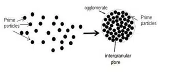
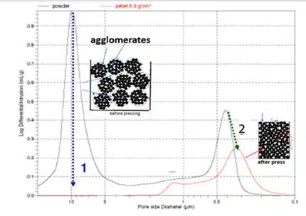
    The die is filled only with agglomerated powder, providing the necessary flowability and specific bulk density (SBD), ensuring uniform mold filling. During process pressing, the agglomerate distraction is illustrated by prosimetra data (see Fig. 5).

    • Large Pores (Peak 1): These are inter-agglomerate pores in the powder, that distractive during pressing.
    • Small Pores (Peak 2): These are pores of the primary powder particles formed, as a result, of agglomerate distractive during pressing.

    Stress-Strain Curve Parameters Description

    The parameters of the stress-strain curve of sintered pellets reflect the characteristics of their structure, depending on the primary powder particles. The stress-strain curve provides information about the mechanical properties of the powder, such as yield strength and Young’s modulus (see Fig. 6).

    Figure 6. Stress-strain curve and parameters used to describe it

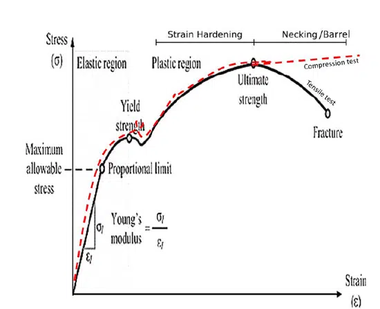
    Yield Strength (Ay): Ay depends on neck size. The latter affects the value of the maximum permissible formation voltage. For porous materials, yield strength can be calculated using the following equation:

    Ay = b * A0 * (X/D) 2 /2/

    , where b is an empirical constant, Ay is the yield strength of the sintered porous material, A0 is the yield strength of the deformed material. Neck size (X) is divided by the primary powder particle size (D), but this ratio cannot exceed 0.5.

    •Young’s Modulus (E): E is related to porosity, which affects capacitance. The behavior of Young’s modulus of porous material, can be described by the following equation

    E = E0 * (1 – p/pc) /3/

    , where E is the modulus of elasticity of the porous material with the corresponding density p, and E0 is the modulus of the solid material at density pc ~ 1.

    The CC curve can be used to calculate the strain hardening coefficient (n), which is related to the defectiveness of the material. This coefficient can influence leakage currents.

    Advantages and Disadvantages of Wet and Mechanical Testing

    Advantages and Disadvantages of Wet Testing

    Capacitance:

    • Reliability: Capacitance testing is reliable for evaluating the final product. It directly depends on the specific surface area of the powder and the anode manufacturing process.
    • Disadvantages: These tests are conducted late, and results may depend on previous processes, making it difficult to assess the initial powder quality when defect correction is no longer possible.

    Leakage Current:

    • Reliability: Leakage current testing is crucial for assessing anode quality, as high leakage currents indicate defects and internal stresses in the anode.
    • Dependence on Defects: High leakage currents can be caused by inhomogeneities and other defects, resulting from low powder quality or improper manufacturing conditions.

    Advantages and Disadvantages of Mechanical Testing

    Advantages:

    Comparison with the benchmark: The presence of a benchmark curve, allows precise comparison of samples and identification of deviations from the norm, making this method more reliable for assessing powder quality.

    • Early Defect Detection: This method, allows to identify of potential issues, at the sintering stage before the pellet proceeds to the next production stage.
    • Objective Assessment of Mechanical Properties: The stress-strain curve provides a comprehensive evaluation of the powder’s overall characteristics, such as particle size distribution width, shape, and chemical purity.

    Disadvantages:

    • Technical Complexity: Mechanical testing requires equipment similar to that used in production for testing the properties of tantalum wire. In the absence of specialists in mechanical testing, specialized programs exist for analyzing stress-strain curves.

    Conclusion

    Since production conditions are determined by the consumer, powder evaluation based on the benchmark stress-strain curve remains an important method for the early detection of potential problems.

    Recommendations

    For a more accurate assessment of tantalum powder quality, in conditions, where anode manufacturing processes, are determined by the tantalum capacitor producer, a comprehensive approach is recommended:

    1. Stress-Strain Curve Comparison with the Standard: Identify and eliminate potential powder defects at the early stages.
    2. Anode Leakage Currents: Check for the absence of defects and internal stresses that may arise during production.
    3. Capacitance: Confirm that the final product meets requirements despite this parameter not being defect-dependent.

    Thus, the integration of these methods will ensure the quality of the powder used and the reliability of tantalum capacitors.

    Reference

    1. THE EFFECT OF MICROSTRUCTURE ON THE MECHANICAL PROPERTIES OF POROUS TANTALUM: AN FEM BASED THE ORIGINAL MODEL Fang, Z., 53rd Annual Meeting of the Orthopedic Research Society
    2. Characterization of Ti–6Al–4V alloy foams synthesized by space holder technique; Z Esen, Ş Bora; Materials Science and Engineering A 528 (2011) 3200–3209
    3. Correlation between Young’s Modulus and Porosity in Porous Materials
    4. J. Kováčik Journal of Materials Science Letters 18(13):1007-1010

    Related

    Source: Vladimir Azbel

    Recent Posts

    Smolteks CNF MIM Capacitor Break 1 µF/mm²

    19.6.2025
    20

    Samsung Electro-Mechanics Releases 0201 X7T 1uF 6.3V MLCC for ADAS Applications

    19.6.2025
    8

    Advanced Conversion Announces Mass Production of 200C Film Capacitors

    18.6.2025
    18

    VinaTech Supercapacitors: Enhancing Smart Meter Reliability and Efficiency

    17.6.2025
    15

    Chinas MLCC Makers Reach 10% Market Share

    16.6.2025
    64

    Smoltek CNF-MIM Capacitor Commercialization Update

    11.6.2025
    31

    Understanding Switched Capacitor Converters

    9.6.2025
    76

    Exxelia to Present Smart Integrated Magnetics and MML Film Capacitors at SIAE25 

    6.6.2025
    36

    What Track Width To Use When Routing PCB

    6.6.2025
    32

    Knowles Extends Range and Performance of C0G MLCC Capacitors

    6.6.2025
    27

    Upcoming Events

    Jun 24
    16:00 - 17:00 CEST

    Limitations of PSFB converters and improvements by a variable inductor ft. Sam Ben-Yaakov

    Jun 24
    17:00 - 18:00 CEST

    Ultra-Compact and Efficient Switched-Capacitor Power Converters

    Jul 23
    13:00 - 14:00 CEST

    PCB design for a Smartwatch

    View Calendar

    Popular Posts

    • Buck Converter Design and Calculation

      0 shares
      Share 0 Tweet 0
    • Boost Converter Design and Calculation

      0 shares
      Share 0 Tweet 0
    • Flyback Converter Design and Calculation

      0 shares
      Share 0 Tweet 0
    • What is a Dielectric Constant and DF of Plastic Materials?

      4 shares
      Share 4 Tweet 0
    • LLC Resonant Converter Design and Calculation

      0 shares
      Share 0 Tweet 0
    • Ripple Current and its Effects on the Performance of Capacitors

      3 shares
      Share 3 Tweet 0
    • How to Design an Inductor

      0 shares
      Share 0 Tweet 0
    • SEPIC Converter Design and Calculation

      0 shares
      Share 0 Tweet 0
    • Dual Active Bridge (DAB) Topology Explained

      0 shares
      Share 0 Tweet 0
    • Why Low ESR Matters in Capacitor Design

      0 shares
      Share 0 Tweet 0

    Newsletter Subscription


    Passive Components Blog

    © EPCI - Leading Passive Components Educational and Information Site

    • Home
    • Privacy Policy
    • EPCI Membership & Advertisement
    • About

    No Result
    View All Result
    • Home
    • Knowledge Blog
    • Premium Suppliers

    © EPCI - Leading Passive Components Educational and Information Site

    This website uses cookies. By continuing to use this website you are giving consent to cookies being used. Visit our Privacy and Cookie Policy.
    Go to mobile version