Passive Components Blog
No Result
View All Result
  • Home
  • NewsFilter
    • All
    • Aerospace & Defence
    • Antenna
    • Applications
    • Automotive
    • Capacitors
    • Circuit Protection Devices
    • electro-mechanical news
    • Filters
    • Fuses
    • Inductors
    • Industrial
    • Integrated Passives
    • inter-connect news
    • Market & Supply Chain
    • Market Insights
    • Medical
    • Modelling and Simulation
    • New Materials & Supply
    • New Technologies
    • Non-linear Passives
    • Oscillators
    • Passive Sensors News
    • Resistors
    • RF & Microwave
    • Telecommunication
    • Weekly Digest

    Vishay Extends Aluminum Capacitors Rating Up to 600 V for DC Links

    Würth Elektronik Introduces Product Navigator for Passive Components

    Panasonic Passive Components for Reliable Robotic Arms

    Littelfuse Unveils Ultra-Low-Power TMR Magnetic Switches

    DC/DC Push‑Pull Converter vs PSFB Design Guide

    Wk 2 Electronics Supply Chain Digest

    Rubycon PMLCAP DC‑Link Film Capacitors in Mass Production

    Bourns SSD‑1000A AEC‑Q Digital Current Sensors

    YAGEO High‑Capacitance X7R Automotive MLCC Extensions

    Trending Tags

    • Ripple Current
    • RF
    • Leakage Current
    • Tantalum vs Ceramic
    • Snubber
    • Low ESR
    • Feedthrough
    • Derating
    • Dielectric Constant
    • New Products
    • Market Reports
  • VideoFilter
    • All
    • Antenna videos
    • Capacitor videos
    • Circuit Protection Video
    • Filter videos
    • Fuse videos
    • Inductor videos
    • Inter-Connect Video
    • Non-linear passives videos
    • Oscillator videos
    • Passive sensors videos
    • Resistor videos

    One‑Pulse Characterization of Nonlinear Power Inductors

    Thermistor Linearization Challenges

    Coaxial Connectors and How to Connect with PCB

    PCB Manufacturing, Test Methods, Quality and Reliability

    Transformer Behavior – Current Transfer and Hidden Feedback

    Choosing the Right Capacitor: The Importance of Accurate Measurements

    RF Inductors: Selection and Design Challenges for High-Frequency Circuits

    Transformer Safety IEC 61558 Standard

    3-Phase EMI Filter Design, Simulation, Calculation and Test

    Trending Tags

    • Capacitors explained
    • Inductors explained
    • Resistors explained
    • Filters explained
    • Application Video Guidelines
    • EMC
    • New Products
    • Ripple Current
    • Simulation
    • Tantalum vs Ceramic
  • Knowledge Blog
  • Suppliers
    • Who is Who
  • PCNS
    • PCNS 2025
    • PCNS 2023
    • PCNS 2021
    • PCNS 2019
    • PCNS 2017
  • Events
No Result
View All Result
Passive Components Blog
No Result
View All Result

Coupled Inductors in SEPIC versus Flyback Converters

26.8.2025
Reading Time: 5 mins read
A A

prof. Sam Ben-Yaakov in this video provides intuitive explanation of the coupled inductors in SEPIC converters and its comparison to Flyback topology converters.

This presentation introduces an intuitive explanation of the coupled inductors SEPIC (Single-Ended Primary Inductor Converter) converter in comparison to the Flyback topology.

RelatedPosts

One‑Pulse Characterization of Nonlinear Power Inductors

Thermistor Linearization Challenges

Transformer Behavior – Current Transfer and Hidden Feedback

Overview of Flyback Converter

The Flyback converter is a widely-used topology in power electronics. Its basic configuration includes:

  • Transistor (Switch): Controls the energy transfer.
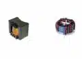
  • Coupled Inductor (Transformer): Facilitates energy storage and transfer.

Operation:

  • Transistor ON: Current flows through the primary winding of the inductor, storing energy.
  • Transistor OFF: The stored energy is released through the secondary winding to the output load.

Both Continuous Conduction Mode (CCM) and Discontinuous Conduction Mode (DCM) are feasible, depending on the load and design.

further reference: Flyback Converter Design and Calculation

Introduction to SEPIC Converter

The SEPIC topology was developed at IBM and has two primary configurations:

  1. Uncoupled Version: Utilizes two separate inductors, a transistor, a capacitor, and a rectifier.
  2. Coupled Inductors Version: Features coupled inductors, a capacitor, and a rectifier.

Key Characteristics:

  • The presence of a capacitor necessitates a shared ground, making SEPIC a non-isolated topology.
  • Despite structural differences, SEPIC and Flyback share fundamental operational principles.

further reference:

  • SEPIC Converter Design and Calculation
  • SEPIC Converter with Coupled and Uncoupled Inductors

Comparative Analysis of SEPIC and Flyback Topologies

  1. Transfer Ratio:
    • Both topologies exhibit similar voltage transfer ratios.
  2. Operation with Transistor ON:
    • In SEPIC, the capacitor is directly connected to the secondary inductor. The voltage across the primary matches the input voltage.
  3. Operation with Transistor OFF:
    • The current flows from the secondary inductor to the output. The loop voltage sums to zero, indicating no need for capacitor charge redistribution between states.

Impact of Coupling Coefficient

  • Flyback: High coupling coefficients minimize oscillations, but leakage inductance leads to energy losses, reducing efficiency.
  • SEPIC: Operates optimally with slight leakage (coupling coefficient < 1). Leakage energy is recycled, enhancing efficiency and mitigating oscillations.

Simulation Insights

A simulation compared both converters under ideal conditions:

  • Ideal Coupling (Coefficient = 1): SEPIC exhibited smooth operation with minimal oscillations, even with large capacitors.
  • Realistic Conditions (Coefficient = 0.99): Flyback exhibited voltage spikes and oscillations, mitigated by adding snubbers and clamps. SEPIC maintained stable performance without additional components.

RMS Current Comparison

  • SEPIC’s RMS current in the primary inductor is significantly lower than that of the Flyback, contributing to better efficiency.

Key Takeaways

  1. Gain Consistency: Both converters have similar gain characteristics.
  2. Design Flexibility: Flyback allows for variable turns ratios, offering greater output voltage flexibility.
  3. Isolation: Flyback provides isolation; SEPIC does not.
  4. Efficiency: SEPIC exhibits higher efficiency due to recycled leakage energy.
  5. Component Requirements: SEPIC reduces the need for snubbers and clamps, simplifying design.
  6. EMI Performance: SEPIC generates less EMI compared to Flyback.

Conclusion

While SEPIC might seem complex, it offers significant benefits, especially in applications requiring stable, efficient power conversion with minimal EMI. Its similarities to Flyback topology simplify the learning curve, making it an excellent choice for various power management scenarios.

Related

Source: Sam Ben-Yaakov

Recent Posts

Würth Elektronik Introduces Product Navigator for Passive Components

14.1.2026
30

Panasonic Passive Components for Reliable Robotic Arms

14.1.2026
36

DC/DC Push‑Pull Converter vs PSFB Design Guide

12.1.2026
42

How Metal Prices Are Driving Passive Component Price Hikes

8.1.2026
271

Modelithics COMPLETE Library v25.8 for Keysight ADS

7.1.2026
35

Taiyo Yuden Releases 165C Automotive Multilayer Metal Power Inductor in 1608 Size

7.1.2026
35

Energy-Controlled Structural Evolution of Amorphous Ta₂O₅ in Tantalum Anodes

6.1.2026
46

2025 Top Passive Components Blog Articles

5.1.2026
108

Exxelia Releases Custom Smart Integrated Magnetics for Space Applications

5.1.2026
58

Upcoming Events

Jan 21
18:00 - 18:45 CET

To Rogowski or not to Rogowski

Jan 27
16:00 - 17:00 CET

Simplifying Vehicle Development with Automotive Ethernet and Zonal Smart Switch Technologies

Feb 24
16:00 - 17:00 CET

Designing Qi2 Wireless Power Systems: Practical Development and EMC Optimization

View Calendar

Popular Posts

  • Buck Converter Design and Calculation

    0 shares
    Share 0 Tweet 0
  • Boost Converter Design and Calculation

    0 shares
    Share 0 Tweet 0
  • LLC Resonant Converter Design and Calculation

    0 shares
    Share 0 Tweet 0
  • Flyback Converter Design and Calculation

    0 shares
    Share 0 Tweet 0
  • Ripple Current and its Effects on the Performance of Capacitors

    3 shares
    Share 3 Tweet 0
  • MLCC and Ceramic Capacitors

    0 shares
    Share 0 Tweet 0
  • Dual Active Bridge (DAB) Topology

    0 shares
    Share 0 Tweet 0
  • What is a Dielectric Constant and DF of Plastic Materials?

    4 shares
    Share 4 Tweet 0
  • How Metal Prices Are Driving Passive Component Price Hikes

    0 shares
    Share 0 Tweet 0
  • SEPIC Converter Design and Calculation

    0 shares
    Share 0 Tweet 0

Newsletter Subscription


Passive Components Blog

© EPCI - Leading Passive Components Educational and Information Site

  • Home
  • Privacy Policy
  • EPCI Membership & Advertisement
  • About

No Result
View All Result
  • Home
  • Knowledge Blog
  • PCNS

© EPCI - Leading Passive Components Educational and Information Site

This website uses cookies. By continuing to use this website you are giving consent to cookies being used. Visit our Privacy and Cookie Policy.
Go to mobile version