Passive Components Blog
No Result
View All Result
  • Home
  • NewsFilter
    • All
    • Aerospace & Defence
    • Antenna
    • Applications
    • Automotive
    • Capacitors
    • Circuit Protection Devices
    • electro-mechanical news
    • Filters
    • Fuses
    • Inductors
    • Industrial
    • Integrated Passives
    • inter-connect news
    • Market & Supply Chain
    • Market Insights
    • Medical
    • Modelling and Simulation
    • New Materials & Supply
    • New Technologies
    • Non-linear Passives
    • Oscillators
    • Passive Sensors News
    • Resistors
    • RF & Microwave
    • Telecommunication
    • Weekly Digest

    Würth Elektronik Updates REDEXPERT DC‑DC Converter Designer

    Stackpole Unveils High-Temperature Automotive Thick Film Chip Resistors for Harsh Environments

    Molex Presents MiniMix Hybrid Power and Signal Connectors for Compact Humanoid Joints

    Bourns Releases Custom SiC AFE/PFC Power Inductor for High‑Voltage Designs

    Littelfuse Releases Toggle Safety Covers for Reliable Control Panels

    Bourns Expanded Blend‑Balance Guitar Potentiometers Resistance Range

    TDK Extends Vibration‑Resistant Axial Aluminum Capacitors for Compact DC‑links

    YAGEO Releases SMD 0402 Pt Temperature Sensors for Space‑Constrained Designs

    Bourns Introduces Automotive Wide Terminal Metal Foil Current Sense Resistors for High‑Reliability Designs

    Trending Tags

    • Ripple Current
    • RF
    • Leakage Current
    • Tantalum vs Ceramic
    • Snubber
    • Low ESR
    • Feedthrough
    • Derating
    • Dielectric Constant
    • New Products
    • Market Reports
  • VideoFilter
    • All
    • Antenna videos
    • Capacitor videos
    • Circuit Protection Video
    • Filter videos
    • Fuse videos
    • Inductor videos
    • Inter-Connect Video
    • Non-linear passives videos
    • Oscillator videos
    • Passive sensors videos
    • Resistor videos

    Current Sense Transformers: Ferrite vs Nanocrystalline Cores for Accurate Current Measurement

    EMC Design Fundamentals: Safe Use of Varistors and Common Mode Chokes in Mains and Data-Line Filters

    Ferrite versus Nanocrystalline Power Inductor Cores: Turns, Gap and Size

    KYOCERA AVX Presents Antenna Integrator Studio Tutorial for Antenna Placement and RF Design

    Power Design Simulation Tools for Faster Inductor Selection and Loss Optimization

    EMC‑Compliant PCB and Connector Design Guidelines

    Why Isolated DC/DC Power Supplies Fail Late, Würth Elektronik Podcast

    Designing 800 V DC EMC Filters: Calculation, Simulation and Measurement

    Current Sense Transformer Datasheet and Design‑in Guide

    Trending Tags

    • Capacitors explained
    • Inductors explained
    • Resistors explained
    • Filters explained
    • Application Video Guidelines
    • EMC
    • New Products
    • Ripple Current
    • Simulation
    • Tantalum vs Ceramic
  • Knowledge Blog
  • Dossiers
    • AI Hardware Dossier
    • Power Converter Dossier
    • Automotive Dossier
    • Capacitor Dossier
    • Resistor Dossier
    • Inductor Dossier
    • Circuit Protection Dossier
  • Suppliers
    • Who is Who
  • PCNS
    • PCNS 2025
    • PCNS 2023
    • PCNS 2021
    • PCNS 2019
    • PCNS 2017
  • Events
  • Home
  • NewsFilter
    • All
    • Aerospace & Defence
    • Antenna
    • Applications
    • Automotive
    • Capacitors
    • Circuit Protection Devices
    • electro-mechanical news
    • Filters
    • Fuses
    • Inductors
    • Industrial
    • Integrated Passives
    • inter-connect news
    • Market & Supply Chain
    • Market Insights
    • Medical
    • Modelling and Simulation
    • New Materials & Supply
    • New Technologies
    • Non-linear Passives
    • Oscillators
    • Passive Sensors News
    • Resistors
    • RF & Microwave
    • Telecommunication
    • Weekly Digest

    Würth Elektronik Updates REDEXPERT DC‑DC Converter Designer

    Stackpole Unveils High-Temperature Automotive Thick Film Chip Resistors for Harsh Environments

    Molex Presents MiniMix Hybrid Power and Signal Connectors for Compact Humanoid Joints

    Bourns Releases Custom SiC AFE/PFC Power Inductor for High‑Voltage Designs

    Littelfuse Releases Toggle Safety Covers for Reliable Control Panels

    Bourns Expanded Blend‑Balance Guitar Potentiometers Resistance Range

    TDK Extends Vibration‑Resistant Axial Aluminum Capacitors for Compact DC‑links

    YAGEO Releases SMD 0402 Pt Temperature Sensors for Space‑Constrained Designs

    Bourns Introduces Automotive Wide Terminal Metal Foil Current Sense Resistors for High‑Reliability Designs

    Trending Tags

    • Ripple Current
    • RF
    • Leakage Current
    • Tantalum vs Ceramic
    • Snubber
    • Low ESR
    • Feedthrough
    • Derating
    • Dielectric Constant
    • New Products
    • Market Reports
  • VideoFilter
    • All
    • Antenna videos
    • Capacitor videos
    • Circuit Protection Video
    • Filter videos
    • Fuse videos
    • Inductor videos
    • Inter-Connect Video
    • Non-linear passives videos
    • Oscillator videos
    • Passive sensors videos
    • Resistor videos

    Current Sense Transformers: Ferrite vs Nanocrystalline Cores for Accurate Current Measurement

    EMC Design Fundamentals: Safe Use of Varistors and Common Mode Chokes in Mains and Data-Line Filters

    Ferrite versus Nanocrystalline Power Inductor Cores: Turns, Gap and Size

    KYOCERA AVX Presents Antenna Integrator Studio Tutorial for Antenna Placement and RF Design

    Power Design Simulation Tools for Faster Inductor Selection and Loss Optimization

    EMC‑Compliant PCB and Connector Design Guidelines

    Why Isolated DC/DC Power Supplies Fail Late, Würth Elektronik Podcast

    Designing 800 V DC EMC Filters: Calculation, Simulation and Measurement

    Current Sense Transformer Datasheet and Design‑in Guide

    Trending Tags

    • Capacitors explained
    • Inductors explained
    • Resistors explained
    • Filters explained
    • Application Video Guidelines
    • EMC
    • New Products
    • Ripple Current
    • Simulation
    • Tantalum vs Ceramic
  • Knowledge Blog
  • Dossiers
    • AI Hardware Dossier
    • Power Converter Dossier
    • Automotive Dossier
    • Capacitor Dossier
    • Resistor Dossier
    • Inductor Dossier
    • Circuit Protection Dossier
  • Suppliers
    • Who is Who
  • PCNS
    • PCNS 2025
    • PCNS 2023
    • PCNS 2021
    • PCNS 2019
    • PCNS 2017
  • Events
No Result
View All Result
Passive Components Blog
No Result
View All Result

SEPIC Converter with Coupled and Uncoupled Inductors

26.8.2025
Reading Time: 7 mins read
A A

Würth Elektronik publishes AppNote with tips for designing SEPIC converters using coupled and uncoupled inductors.

Würth Elektronik addresses the operation of a Single-Ended Primary-Inductor-Converter (SEPIC) in both continuous and discontinuous conduction modes (CCM and DCM). The 28-page document also includes design considerations and guidelines with focus on the power magnetics.

RelatedPosts

Würth Elektronik Updates REDEXPERT DC‑DC Converter Designer

Würth Elektronik Coupled Inductors Harnessing Leakage Inductance in SEPIC, ZETA and Ćuk Converters

EMC Design Fundamentals: Safe Use of Varistors and Common Mode Chokes in Mains and Data-Line Filters

The SEPIC is a non-isolated switching power supply topology generating an output voltage that can be higher, equal or lower than the input voltage. Typical applications include battery-powered devices and chargers, automotive power systems, photovoltaic converters, LED lighting, and power factor correction stages.

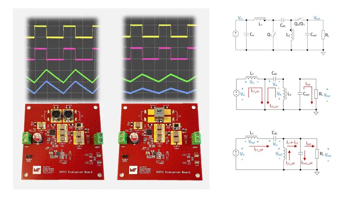
This new Application Note from Würth Elektronik provides a detailed analysis of the SEPIC converter with particular emphasis on the implementation with a coupled inductor, such as the WE-MCRI. It also includes an analysis of “ripple current steering” technique and the key role that the leakage inductance plays in the converter, all supported by SPICE simulations and measurements on a real DC-DC SEPIC converter prototype.

Coupled or uncoupled

Unlike topologies with a single inductor, such as buck, boost or buck-boost converters, the SEPIC power stage requires two inductors. These can be implemented as uncoupled, separate inductors, or alternatively configured as a coupled power inductor with two windings on a common core. This configuration not only reduces the number of components but also requires less inductance to generate the same ripple current amplitude compared to a solution with uncoupled inductors. Moreover, the magnetic coupling of the windings enables the implementation of “ripple current steering”. This is a technique in which the ripple current of the input winding can be “steered” to the output winding, helping to reduce conducted EMI noise. “When designing a SEPIC with coupled inductors, it is important to understand the influence of the coupling factor on the converter performance. In contrast to typical scenarios, a higher leakage inductance can be of advantage in this case,” explains Eleazar Falco, Senior Application Engineer at Würth Elektronik eiSos and author.

Introduction

The SEPIC can produce an output voltage higher or lower than the input, maintaining the same polarity. This makes it valuable in systems with fluctuating supply or load conditions, such as photovoltaic converters, automotive electronics, LED drivers, and battery chargers.
The note discusses:

  • CCM and DCM operation
  • Component selection and calculation
  • Influence of inductor coupling, leakage inductance, and ripple current steering
  • Simulation and real measurement data from prototype hardware

Key Points

  • Topology Basics: SEPIC combines boost-like input current (continuous) and buck-boost-like output (discontinuous), connected via an AC coupling capacitor (CAC).
  • Coupled vs. Uncoupled Inductors: Coupling can reduce ripple current by up to 50% and enable ripple steering to reduce EMI.
  • Operating Modes: Analysis covers Continuous Conduction Mode (CCM), Boundary mode, and Discontinuous Conduction Mode (DCM).
  • Design Equations: Provided for inductors, capacitors, switches, duty cycle, and current/voltage stresses.
  • Ripple Current Steering: Intentional imbalance in winding turns, leakage inductance, or volt-seconds can shift ripple from one winding to the other, reducing EMI filter requirements.
  • Leakage Inductance: Often considered a parasitic, but here shown as beneficial for ripple steering tolerance.
  • Measurements & Validation: SPICE simulations closely matched to experimental results on real boards.

Extended Summary

SEPIC Principle of Operation

The document explains how a SEPIC converter works — a type of DC‑DC converter that can step voltage up or down without changing polarity. It’s often used in electronics like car systems, solar converters, LED lighting, and battery chargers. The note compares two design styles:

  • Using two separate inductors
  • Using a coupled inductor (two windings on one magnetic core)

It also covers how to choose components, the differences between operating in continuous vs discontinuous conduction modes, and how to use ripple current steering to cut down on electromagnetic interference (EMI).

The SEPIC power stage (Fig. 1) uses two inductors (L1, L2), AC coupling capacitor (CAC), output capacitor (Cout), control transistor (Q1), and diode or synchronous switch (Q2/D1). The AC capacitor blocks DC transfer while allowing AC energy transfer, also providing inherent output short-circuit protection.
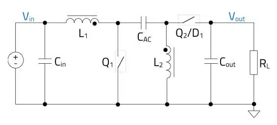
Figure 1 : SEPIC power stage

Key Takeaways

  • How it works: SEPIC transfers energy through an AC‑coupling capacitor between two inductor stages.
  • Two inductors or one core: Coupling windings can shrink ripple currents and allow EMI‑reducing tricks.
  • Two main modes:
    • CCM (Continuous Conduction Mode): Inductor currents never drop to zero.
    • DCM (Discontinuous Conduction Mode): Inductor currents hit zero part of the cycle, more common at light load.
  • Ripple current steering: Deliberately shifting current ripple from one winding to the other can reduce EMI filtering needs.
  • Leakage inductance: Normally unwanted, but here it can improve tolerance to design imbalances.

How the SEPIC Operates

  1. On phase (switch closed): Both inductors store energy; load is fed by the output capacitor.
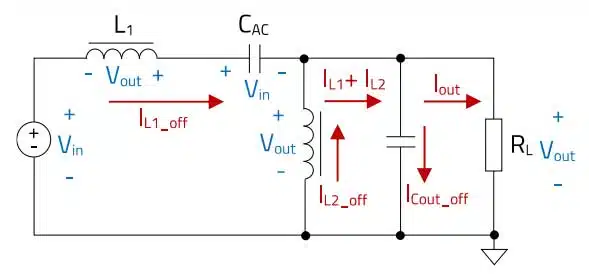
  2. Off phase (switch open): Inductors release energy through the coupling capacitor to the load.
  3. The average voltage‑time across each inductor balances out over a switching cycle.
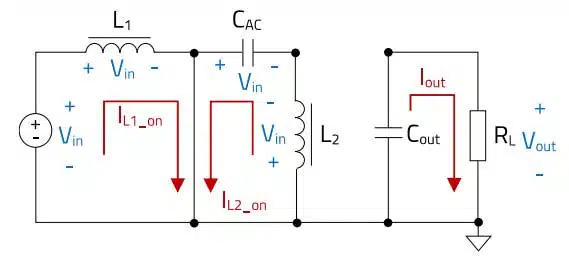
Figure 2. : Equivalent circuit during the on-time of Q 1 (∆ton )
Figure 3 : Equivalent circuit during the off -time of Q 1 (∆t off )

Coupled vs. Uncoupled Inductors

  • Separate inductors: Simpler, easier to source, but higher ripple currents.
  • Coupled inductors: Can halve ripple amplitude for the same inductance; make ripple steering possible.

Ripple Current Steering

By tweaking:

  • Turns ratio between windings
  • Leakage inductance
  • Volt‑second applied per winding
    you can redirect most ripple to one side, reducing it on the input side and easing EMI filter design.

Why Leakage Can Help

A bit of leakage inductance makes ripple steering less sensitive to part‑to‑part variations, so performance stays more consistent in real‑world builds.

Conclusion

The SEPIC is a flexible voltage converter. Coupled inductors and ripple steering can improve efficiency, cut costs, and reduce EMI filters — especially in custom, higher‑power designs. For smaller projects, the benefit might not outweigh the added complexity.

Download the full application note in pdf from Würth Elektronik website: ANP135

Further read:

  • SEPIC Converter Design and Calculation
  • Coupled Inductors in SEPIC versus Flyback Converters

Related

Source: Würth Elektronik

Recent Posts

Würth Elektronik Updates REDEXPERT DC‑DC Converter Designer

6.8.2026
26

Bourns Releases Custom SiC AFE/PFC Power Inductor for High‑Voltage Designs

6.8.2026
24

Current Sense Transformers: Ferrite vs Nanocrystalline Cores for Accurate Current Measurement

5.8.2026
44

Murata Releases 1210 Metal Terminal Common Mode Choke for 10Base‑T1S In‑Vehicle Ethernet

30.7.2026
141

Würth Elektronik Coupled Inductors Harnessing Leakage Inductance in SEPIC, ZETA and Ćuk Converters

29.7.2026
97

TDK Releases SMD Common‑Mode Chokes for Compact High‑Current EMI Filtering

28.7.2026
96

Exxelia Offers 1200V Capacitors and Magnetics for 800V Aerospace Platforms

22.7.2026
74

Bourns Introduces Automotive BMS Signal Transformer with Integrated Common Mode Chokes

17.7.2026
58

Bourns Introduces Automotive Shielded Power Inductors for Compact DC‑DC Converters

16.7.2026
85

Upcoming Events

Sep 10
11:00 - 12:00 CEST

Equipment models and model strategies for Space Missions

Sep 29
16:00 - 17:00 CEST

Cybersecurity 2026

Nov 24
16:00 - 17:00 CET

Component selection with the WE REDEXPERT® DC-DC Converter Designer Tool

View Calendar

Popular Posts

  • Buck Converter Design and Calculation

    0 shares
    Share 0 Tweet 0
  • Boost Converter Design and Calculation

    0 shares
    Share 0 Tweet 0
  • LLC Resonant Converter Design and Calculation

    0 shares
    Share 0 Tweet 0
  • Flyback Converter Design and Calculation

    0 shares
    Share 0 Tweet 0
  • YAGEO Announces July 2026 Capacitor Price Increase

    0 shares
    Share 0 Tweet 0
  • MLCC and Ceramic Capacitors

    0 shares
    Share 0 Tweet 0
  • MLCCs in the Age of AI: Q2 2026 Market Tightness

    0 shares
    Share 0 Tweet 0
  • Earthing Systems and IEC Classification Explained

    0 shares
    Share 0 Tweet 0
  • Dual Active Bridge (DAB) Topology

    0 shares
    Share 0 Tweet 0
  • Ripple Current and its Effects on the Performance of Capacitors

    3 shares
    Share 3 Tweet 0

Newsletter Subscription


Passive Components Blog

© EPCI - Leading Passive Components Educational and Information Site

  • Home
  • Privacy Policy
  • EPCI Membership & Advertisement
  • About

No Result
View All Result
  • Home
  • Knowledge Blog
  • Dossiers
  • PCNS

© EPCI - Leading Passive Components Educational and Information Site