Passive Components Blog
No Result
View All Result
  • Home
  • NewsFilter
    • All
    • Aerospace & Defence
    • Antenna
    • Applications
    • Automotive
    • Capacitors
    • Circuit Protection Devices
    • electro-mechanical news
    • Filters
    • Fuses
    • Inductors
    • Industrial
    • Integrated Passives
    • inter-connect news
    • Market & Supply Chain
    • Market Insights
    • Medical
    • Modelling and Simulation
    • New Materials & Supply
    • New Technologies
    • Non-linear Passives
    • Oscillators
    • Passive Sensors News
    • Resistors
    • RF & Microwave
    • Telecommunication
    • Weekly Digest

    KYOCERA AVX Releases Compact High-Directivity Couplers

    Supercapacitors Emerge as a Promising Solution to AI-Induced Power Energy Spikes

    Wk 18 Electronics Supply Chain Digest

    YAGEO Releases High Current SMD Common Mode Choke With Shape Core Construction

    Murata and NIMS Built New Database of Dielectric Material Properties

    Tariffs Crush Sales Sentiment in April 2025 ECST Results

    High-Density PCB Assemblies For Space Applications

    Solid State Polymer Multilayer Capacitors For High Temperature Application

    Graphene-Based BOSC Bank Of Supercapacitor Cells

    Trending Tags

    • Ripple Current
    • RF
    • Leakage Current
    • Tantalum vs Ceramic
    • Snubber
    • Low ESR
    • Feedthrough
    • Derating
    • Dielectric Constant
    • New Products
    • Market Reports
  • VideoFilter
    • All
    • Antenna videos
    • Capacitor videos
    • Circuit Protection Video
    • Filter videos
    • Fuse videos
    • Inductor videos
    • Inter-Connect Video
    • Non-linear passives videos
    • Oscillator videos
    • Passive sensors videos
    • Resistor videos

    Coupled Inductors in Multiphase Boost Converters

    VPG Demonstrates Precision Resistor in Cryogenic Conditions

    Comparison Testing of Chip Resistor Technologies Under High Vibration

    EMC Challenges for High Speed Signal Immunity and Low EMI

    MOSFET Gate Drive Resistors Power Losses

    Modified Magnetic Reluctance Equivalent Circuit and its Implications

    Improving Common Mode Noise Reduction while Decreasing BOM

    Die and Wire PCB Bonding Explained

    Rogowski Coil Current Sensor Explained

    Trending Tags

    • Capacitors explained
    • Inductors explained
    • Resistors explained
    • Filters explained
    • Application Video Guidelines
    • EMC
    • New Products
    • Ripple Current
    • Simulation
    • Tantalum vs Ceramic
  • Knowledge Blog
  • Suppliers
    • Who is Who
  • Events
No Result
View All Result
Passive Components Blog
No Result
View All Result

DC Bias Characteristics of Ceramic Capacitors

23.2.2023
Reading Time: 7 mins read
A A

This blog article written by Simon Cen, KYOCERA-AVX Corporation explains DC BIAS characteristics of ceramic capacitors and its design implications.

Introduction

Most electrical engineers are at least familiar with the different ratings of ceramic capacitors, such as C0G and X7R. In many applications, the meaning of these character codes is relatively unimportant as some other factor, like price or size, may be driving component selection.

RelatedPosts

KYOCERA AVX Releases Compact High-Directivity Couplers

Kyocera Introducing SAW Filters for Implantable Medical and AED Applications

The Path to Thinner MLCCs and Innovative Capacitor Development

Designers must be wary, however, as choosing the wrong combination of capacitor dielectric and applied voltage can have critical performance implications for the associated circuit. For class two dielectrics, the change in bulk capacitance with MLCC DC bias can be substantial. Understanding why this happens and how to choose a proper ceramic capacitor can eliminate this common pitfall.

Multilayer ceramic capacitors (MLCC) have many advantages in modern electronic design, including small size, high withstand voltage, and long service life. They have become the first choice of engineers for most common bulk capacitance needs, including precision filters, resonators, power supply bypass devices, and decoupling elements.

Figure 1: Basic MLCC construction

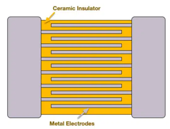
The basic structure of MLCC’s is shown in Figure 1, where a ceramic insulator separates multiple metal electrodes. The geometry of the electrodes, the thickness of the dielectric insulator, and material properties of the ceramic all factor into the total capacitance and the second-order dependencies.

Typically, MLCC’s are divided into class 1 and 2 devices based on their dielectric material properties. Class 1 capacitors are the most robust with the fewest sensitivities and are usually built from TiO2. They also exhibit lower capacitance per unit volume and are often employed in high precision circuits requiring constant impedance. Class 2 devices, on the other hand, are denser with higher overall capacitance and are also more sensitive to both temperature and applied DC voltage. This is almost entirely due to the BaTiO3 dielectric and the unique properties this ceramic material exhibits.

The Physics of DC Bias and Temperature Behaviour of MLCC Capacitors

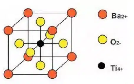
BaTiO3 is a ferroelectric material that exhibits the phenomenon of spontaneous polarization and anti-polarization. It belongs to the perovskite group because it shares oxygen atoms at all four corners in the tetragonal phase, as shown in Figure 2.

BaTiO3 is an ideal material for manufacturing MLCC’s because of its high dielectric constant at room temperature. For example, the dielectric constant of perovskite BaTiO3 ceramics is as high as 7000, while that of other ceramics, such as TiO2, is between 20 and 70. For these reasons, BaTiO3 has become the best choice for manufacturing high capacitance multilayer ceramic capacitors.

Figure 2. BaTiO3 in the tetragonal phase
Figure 3. Temperature dependence of crystal structure and resulting dielectric constant for BaTiO3

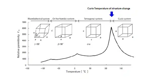
When the temperature is lower than the Curie point, one crystal axis (c-axis) elongates. The other crystal axis shrinks slightly and changes to the tetragonal phase, as shown in Figure 3. At this point, the tetravalent Ti atom located in the axial direction of the cell is far away from the center of the cell and polarized. In other words, when the temperature is lower than the Curie point, the crystal structure appears asymmetric. This type of polarization is called self polarization, and the effect of temperature on the dielectric constant is significant.

BaTiO3 ceramics are a microcrystalline aggregate (polycrystal) with a submicron diameter. These fine crystals are called grains, and the crystal structure is arranged, as shown in Figure 4. When the temperature is lower than the Curie point, these grains are randomly divided into domains in many directions. In each domain, the crystal axis direction is the same in each domain, known as spontaneous polarization. When BaTiO3 ceramics are heated above the Curie point, the crystal structure changes from tetragonal to cubic phase, and the spontaneous polarization domain disappears.

Figure 4. Microstructure of BaTiO3 ceramics

Similarly, when it is cooled below the Curie temperature, the cubic phase changes to the tetragonal phase, and the grains are squeezed to produce stress. Below this temperature point, a small number of small domains appear in the grain, and the spontaneous polarization of each domain can be easily reversed by a low-intensity electric field. Because the relative dielectric constant corresponds to the spontaneous polarization per unit volume, a very high capacitance value can be obtained.

The change of capacitance with applied voltage does not lie in the spontaneous polarization of the domain in the grain structure but in the reversal of spontaneous polarization, which affects the relative dielectric constant. When the spontaneous polarization is reversed without electric field stress (DC bias), MLCC’s exhibit a high dielectric constant and a high capacitance value.

When the external electric field acts on the self polarization process, the spontaneous polarization reversal is unlikely, and the capacitance value will be much lower. This mechanism is responsible for decreasing capacitance under the action of DC bias.

Design Implications

Many engineers are used to the qualities and nuances of tantalum capacitors and aluminum electrolytic capacitors in circuit design. They are constructed from non-ferroelectric, low dielectric constant materials, and their high capacitance values are obtained through the very high electrode area and minuscule dielectric thickness.

Unlike MLCC’s, their capacitance is independent of the voltage applied. Therefore, it is necessary for design engineers to understand the DC bias characteristics of ceramic capacitors and how different materials and manufacturing techniques impact them. The DC bias characteristics of MLCC’s vary with different dielectric temperature coefficients.

Figure 5. DC bias effect on capacitance for different capacitor classes

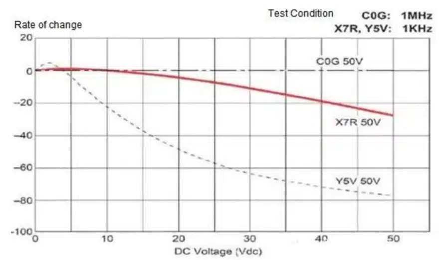
Ceramic capacitors made by class 1 dielectrics (COG, u2j, etc.) with temperature compensation are paraelectric ceramics, and the capacitance value will not change much with the applied voltage. Class 2 ceramic capacitors built with BaTiO3 dielectric (X7R, X5R, etc.) exhibit a substantial decrease in capacitance value under increasing DC bias. A comparison is shown in Figure 5. for several different ceramic capacitors.

Figure 6. KYOCERA AVX 1210, 50V, 2.2uF MLCC DC voltage curve

To reduce the influence of DC bias, ceramic capacitor manufacturers use different kinds of rare metals to adjust BaTiO3 based crystals. Because other manufacturers use different compositions, the DC bias characteristics of ceramic capacitors are also different. The electrical design engineer must research the differences in DC bias characteristics among other manufacturers during the component selection phase.

Unlike many other families of capacitors, MLCC’s come in different classes with surprising temperature and DC voltage dependencies. In addition, these dependencies can vary from manufacturer to manufacturer and require designers to research their component selections carefully.

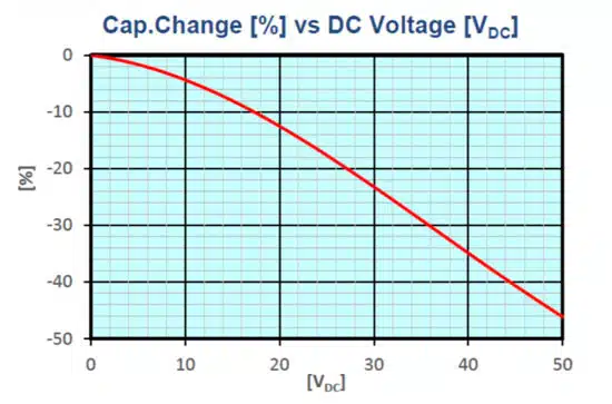
As a leading passive device manufacturer, KYOCERA AVX has been focusing on researching ceramic capacitor technology for decades and has rich experience in improving the DC bias characteristics of ceramic capacitors. One example is shown in Figure 6, where the drop in capacitance across the voltage rating is only 45%, a significant improvement compared to many competitive options.

Understanding the DC bias dependency and the associated tradeoffs is critical to a successful design.

Further Reference: High CV MLCC DC BIAS and AGEING Capacitance Loss Explained

Related

Source: KYOCERA AVX

Recent Posts

KYOCERA AVX Releases Compact High-Directivity Couplers

7.5.2025
10

Supercapacitors Emerge as a Promising Solution to AI-Induced Power Energy Spikes

6.5.2025
31

Murata and NIMS Built New Database of Dielectric Material Properties

5.5.2025
38

Tariffs Crush Sales Sentiment in April 2025 ECST Results

5.5.2025
52

Solid State Polymer Multilayer Capacitors For High Temperature Application

2.5.2025
19

Graphene-Based BOSC Bank Of Supercapacitor Cells

2.5.2025
12

Hybrid Energy Storage System for Nanosatellite Applications

1.5.2025
9

COTS-Plus Bulk Tantalum Capacitor for LEO Flight Platforms

29.4.2025
37

Würth Elektronik Offers New Power Supplies Development Kit

29.4.2025
37

High Energy Density Supercapacitors for Space Applications

28.4.2025
34

Upcoming Events

May 14
11:00 - 12:00 CEST

Reliable RIGID.flex PCBs for Critical Applications – Made in Europe

May 28
16:00 - 17:00 CEST

Power Over Data Line

View Calendar

Popular Posts

  • Buck Converter Design and Calculation

    0 shares
    Share 0 Tweet 0
  • Boost Converter Design and Calculation

    0 shares
    Share 0 Tweet 0
  • Flyback Converter Design and Calculation

    0 shares
    Share 0 Tweet 0
  • Tariffs Crush Sales Sentiment in April 2025 ECST Results

    0 shares
    Share 0 Tweet 0
  • What is a Dielectric Constant and DF of Plastic Materials?

    4 shares
    Share 4 Tweet 0
  • LLC Resonant Converter Design and Calculation

    0 shares
    Share 0 Tweet 0
  • Ripple Current and its Effects on the Performance of Capacitors

    3 shares
    Share 3 Tweet 0
  • Flying Capacitors Explained

    0 shares
    Share 0 Tweet 0
  • Supercapacitors Emerge as a Promising Solution to AI-Induced Power Energy Spikes

    0 shares
    Share 0 Tweet 0
  • How to Design an Inductor

    0 shares
    Share 0 Tweet 0

Newsletter Subscription


Passive Components Blog

© EPCI - Leading Passive Components Educational and Information Site

  • Home
  • Privacy Policy
  • EPCI Membership & Advertisement
  • About

No Result
View All Result
  • Home
  • Knowledge Blog
  • Premium Suppliers

© EPCI - Leading Passive Components Educational and Information Site

This website uses cookies. By continuing to use this website you are giving consent to cookies being used. Visit our Privacy and Cookie Policy.
Go to mobile version