Passive Components Blog
No Result
View All Result
  • Home
  • NewsFilter
    • All
    • Aerospace & Defence
    • Antenna
    • Applications
    • Automotive
    • Capacitors
    • Circuit Protection Devices
    • electro-mechanical news
    • Filters
    • Fuses
    • Inductors
    • Industrial
    • Integrated Passives
    • inter-connect news
    • Market & Supply Chain
    • Market Insights
    • Medical
    • Modelling and Simulation
    • New Materials & Supply
    • New Technologies
    • Non-linear Passives
    • Oscillators
    • Passive Sensors News
    • Resistors
    • RF & Microwave
    • Telecommunication
    • Weekly Digest

    DigiKey Offers Zephyr Operating System Workshop and Training Videos

    Exxelia to Present Smart Integrated Magnetics and MML Film Capacitors at SIAE25 

    What Track Width To Use When Routing PCB

    YAGEO Unveils PulseChip LAN Transformer

    Bourns Releases Automotive Impedance Matching Transformer

    Stackpole Offers Affordable Current Sense Chip Resistors

    Knowles Extends Range and Performance of C0G MLCC Capacitors

    May 2025 ECST Component Results Show Moderating Decline in Sales Sentiment

    Panasonic Releases New Aluminum Hybrid Capacitors with High Ripple Current in Compact Size

    Trending Tags

    • Ripple Current
    • RF
    • Leakage Current
    • Tantalum vs Ceramic
    • Snubber
    • Low ESR
    • Feedthrough
    • Derating
    • Dielectric Constant
    • New Products
    • Market Reports
  • VideoFilter
    • All
    • Antenna videos
    • Capacitor videos
    • Circuit Protection Video
    • Filter videos
    • Fuse videos
    • Inductor videos
    • Inter-Connect Video
    • Non-linear passives videos
    • Oscillator videos
    • Passive sensors videos
    • Resistor videos

    Coupled Inductors Circuit Model and Examples of its Applications

    Inductor Resonances and its Impact to EMI

    Highly Reliable Flex Rigid PCBs, Würth Elektronik Webinar

    Causes of Oscillations in Flyback Converters

    How to design a 60W Flyback Transformer

    Modeling and Simulation of Leakage Inductance

    Power Inductor Considerations for AI High Power Computing – Vishay Video

    Coupled Inductors in Multiphase Boost Converters

    VPG Demonstrates Precision Resistor in Cryogenic Conditions

    Trending Tags

    • Capacitors explained
    • Inductors explained
    • Resistors explained
    • Filters explained
    • Application Video Guidelines
    • EMC
    • New Products
    • Ripple Current
    • Simulation
    • Tantalum vs Ceramic
  • Knowledge Blog
  • Suppliers
    • Who is Who
  • Events
No Result
View All Result
Passive Components Blog
No Result
View All Result

Designing a Small Integrated 500W LLC Transformer

10.10.2023
Reading Time: 5 mins read
A A

In this blog article Sotiris Zorbas, MSc, Frenetic Power Εlectronics Εngineer is explaining how to design a small integrated LLC transformer for 500W PSU application.

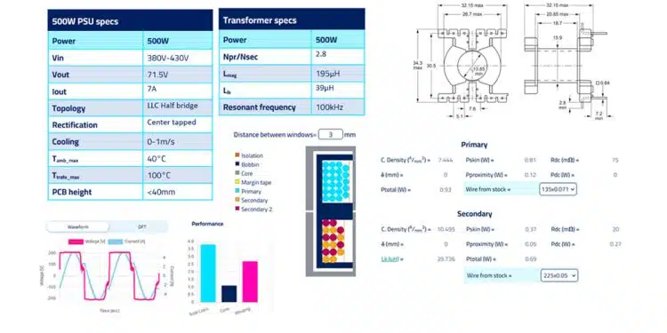
Let’s see the specs of this LLC center tapped PSU that we want to design Magnetics for. We are talking about a charger with 71.5V/7A output:

RelatedPosts

How to design a 60W Flyback Transformer

How to Design LLC Transformer

Leakage Inductance Model; Frenetic Webinar Recording

  • Our cooling conditions can be either natural cooling or some forced cooling up to 1m/s, depending on the position of fan relative to the Magnetics.
  • The intention is for the fan to be mounted on the enclosure, forcing air from the inside of the box to the environment outside. The ambient temperature inside the box is set at 40°C maximum. The fan speed will be controlled based on the core temperature of the Transformer, where a glued NTC inside an M3 bare ring terminal will be also glued to the Transformer core.
  • Using the equations and methodology of the previous Newsletters, we derived the specifications for the Transformer inductances and turns ratio.
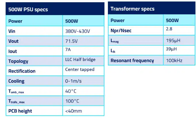
Figure 1. PSU/Transformer specs list

Based on the findings from previous blog

In previous blog, we built some nice 2-chamber Transformers from 500W to 2kW. In all cases, the actual Transformer total losses amounted to approximately 0.6% of the total power delivered to the load. That observation is in line with our experience in Frenetic, and we will use it to minimize our design iterations.

Also, the power density for naturally cooled designs to achieve approx. ~50°C of temperature rise is somewhere between 5-9kW/L. But in our case, we have some variable fan cooling when the Transformer gets hot. That said, we will push power density more than 50% to about 12-15kW/L. Of course, these are preliminary assumptions and should be treated as such.

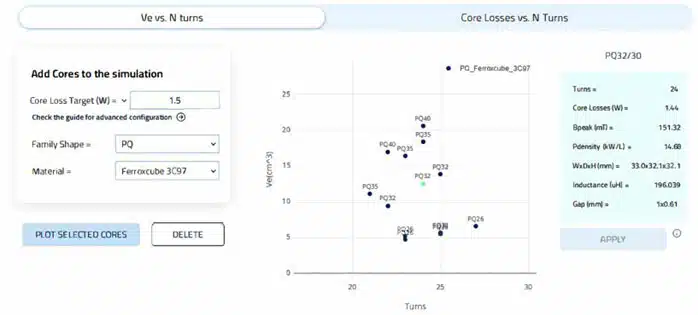
Figure 2.  The Core Optimizer helping us quickly find a core 
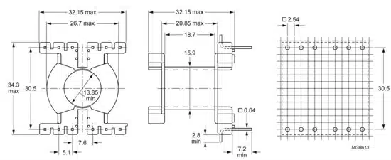
Figure 3.  PQ32/30 Bobbin/Transformer dimensions and PCB pinout

Plotting PQ core sets I quickly found a match for my specifications:

  • As mentioned, 0.6% out of the 500W are set aside for the Transformer losses, and that is 3W. Given a 50-50% split between core-winding losses we set a 1.5W core loss target.
  • From the results shown a PQ32/30 core has a power density of 14.7kW and height at 32mm which if one counts a 1.6mm FR4 and 5mm standoffs is less than the 40mm PCB height that was specified.
  • Also, instead of 24 turns suggested from the tool, 23 turns were selected to better match the turns ratio, given that the secondary turns should be a round number. In this case 7 turns for each secondary.

The windings part

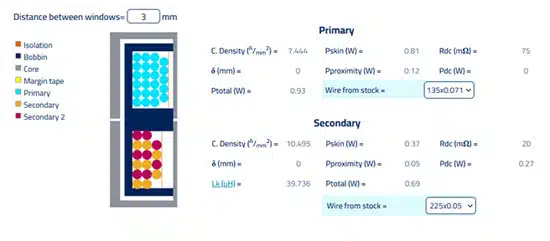
All necessary info for the Winding is here. As you can see in Figure 4., we predict a 39-40 μH of leakage with 3mm of separation. The wires used are simple in stock Litz wires with different strand diameters, and my comment here is that this is a manufacturable design with the necessary margins as far as fitting goes, in place.

Figure 4.  Winding configuration and losses

The worst case condition

  • Assuming natural cooling only.
  • The PFC outputs 380V (input voltage of the LLC converter)
  • Frequency moves down to 84kHz (100kHz is the resonant freq.)
  • The rms currents increase.

We get the following performance:

✅ Tmax at 91°C below 100°C

✅ Pmax = 3.8W in line with our 3W prediction.

✅ Integrated 40μH of leakage inductance

Of course, with air cooling or higher input voltages (close to 400V) the Transformer may as well operate at 50°C under full load!

And the best part: design time, just 2hr!

Related

Source: Frenetic

Recent Posts

Exxelia to Present Smart Integrated Magnetics and MML Film Capacitors at SIAE25 

6.6.2025
8

What Track Width To Use When Routing PCB

6.6.2025
3

YAGEO Unveils PulseChip LAN Transformer

6.6.2025
2

Bourns Releases Automotive Impedance Matching Transformer

6.6.2025
1

5th PCNS Conference Registration Now Open!

5.6.2025
10

Capacitance Definition of Non-Linear Voltage Dependent Capacitors

5.6.2025
12

Bourns Releases Noise Suppression Common Mode SMD Inductors

4.6.2025
13

Passive Electronic Components Lead-times Update

4.6.2025
38

Coilcraft Unveils 165C High-Temperature Coupled Inductors

3.6.2025
11

Murata Expands its Automotive Common Mode Choke Coils to 150C and High Current Capability

29.5.2025
32

Upcoming Events

Jun 24
17:00 - 18:00 CEST

Ultra-Compact and Efficient Switched-Capacitor Power Converters

View Calendar

Popular Posts

  • Buck Converter Design and Calculation

    0 shares
    Share 0 Tweet 0
  • Boost Converter Design and Calculation

    0 shares
    Share 0 Tweet 0
  • Flyback Converter Design and Calculation

    0 shares
    Share 0 Tweet 0
  • What is a Dielectric Constant and DF of Plastic Materials?

    4 shares
    Share 4 Tweet 0
  • LLC Resonant Converter Design and Calculation

    0 shares
    Share 0 Tweet 0
  • Ripple Current and its Effects on the Performance of Capacitors

    3 shares
    Share 3 Tweet 0
  • Dual Active Bridge (DAB) Topology Explained

    0 shares
    Share 0 Tweet 0
  • SEPIC Converter Design and Calculation

    0 shares
    Share 0 Tweet 0
  • Flying Capacitors Explained

    0 shares
    Share 0 Tweet 0
  • How to Design an Inductor

    0 shares
    Share 0 Tweet 0

Newsletter Subscription


Passive Components Blog

© EPCI - Leading Passive Components Educational and Information Site

  • Home
  • Privacy Policy
  • EPCI Membership & Advertisement
  • About

No Result
View All Result
  • Home
  • Knowledge Blog
  • Premium Suppliers

© EPCI - Leading Passive Components Educational and Information Site

This website uses cookies. By continuing to use this website you are giving consent to cookies being used. Visit our Privacy and Cookie Policy.
Go to mobile version