Passive Components Blog
No Result
View All Result
  • Home
  • NewsFilter
    • All
    • Aerospace & Defence
    • Antenna
    • Applications
    • Automotive
    • Capacitors
    • Circuit Protection Devices
    • electro-mechanical news
    • Filters
    • Fuses
    • Inductors
    • Industrial
    • Integrated Passives
    • inter-connect news
    • Market & Supply Chain
    • Market Insights
    • Medical
    • Modelling and Simulation
    • New Materials & Supply
    • New Technologies
    • Non-linear Passives
    • Oscillators
    • Passive Sensors News
    • Resistors
    • RF & Microwave
    • Telecommunication
    • Weekly Digest

    Samsung Electro-Mechanics Releases High-Capacitance MLCCs for AI Server Applications

    Samsung Electro-Mechanics Releases 165C Automotive 0806 Size Power Inductors

    Coupled Inductors Circuit Model and Examples of its Applications

    Würth Elektronik Introduces LTspice Models for ESD Products

    Capacitor Ripple Current Testing: A Design Consideration

    TDK Releases 0201 High-Frequency Smallest Inductors

    Coilcraft Extends Air Core RF Inductors

    Bourns Releases Automotive 1W Flyback Transformer

    Wk 20 Electronics Supply Chain Digest

    Trending Tags

    • Ripple Current
    • RF
    • Leakage Current
    • Tantalum vs Ceramic
    • Snubber
    • Low ESR
    • Feedthrough
    • Derating
    • Dielectric Constant
    • New Products
    • Market Reports
  • VideoFilter
    • All
    • Antenna videos
    • Capacitor videos
    • Circuit Protection Video
    • Filter videos
    • Fuse videos
    • Inductor videos
    • Inter-Connect Video
    • Non-linear passives videos
    • Oscillator videos
    • Passive sensors videos
    • Resistor videos

    Coupled Inductors Circuit Model and Examples of its Applications

    Inductor Resonances and its Impact to EMI

    Highly Reliable Flex Rigid PCBs, Würth Elektronik Webinar

    Causes of Oscillations in Flyback Converters

    How to design a 60W Flyback Transformer

    Modeling and Simulation of Leakage Inductance

    Power Inductor Considerations for AI High Power Computing – Vishay Video

    Coupled Inductors in Multiphase Boost Converters

    VPG Demonstrates Precision Resistor in Cryogenic Conditions

    Trending Tags

    • Capacitors explained
    • Inductors explained
    • Resistors explained
    • Filters explained
    • Application Video Guidelines
    • EMC
    • New Products
    • Ripple Current
    • Simulation
    • Tantalum vs Ceramic
  • Knowledge Blog
  • Suppliers
    • Who is Who
  • Events
No Result
View All Result
Passive Components Blog
No Result
View All Result

ESD Protection by MLCC Ceramic Capacitors

29.11.2022
Reading Time: 7 mins read
A A

This technical blog article written by Oliver Zimmermann and John McCarry, KYOCERA-AVX Components Corporation, explains the functional properties of MLCC ceramic capacitors as an alternative overvoltage and ESD protection.

Introduction – Traditional Electrostatic Protection

Any conductive interface between an electrical circuit and the outside world introduces the possibility of damage through electrostatic discharge (ESD).

RelatedPosts

Capacitor Ripple Current Testing: A Design Consideration

KYOCERA AVX Releases Compact High-Directivity Couplers

Kyocera Introducing SAW Filters for Implantable Medical and AED Applications

Accumulated static charge on a person, a cable, or any similar surface can readily dissipate its stored potential energy upon contact into sensitive components resulting in highly destructive currents.

These voltages can reach the kilovolts and require the addition of specialized circuits and semiconductor devices to protect downstream circuits and ensure continued reliable operation.

Traditional protection devices include a myriad of different varistors and transient voltage suppression (TVS) diodes. Both operate on the principle of shunting current to ground when the applied voltage exceeds a clamping threshold as shown in figure 1.

Figure 1 – TVS diode used to shunt high voltage current to ground

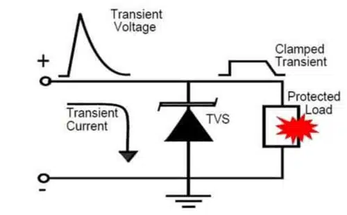
Ideally, varistors and TVS diodes only activate to protect the circuit when a high voltage is present and impart no parasitic effects during normal operation.

For high-speed data lines, in particular, it is critical that the protection device introduce as little capacitance as possible (Electronic Design). TVS diodes and varistors are therefore specified not only by their voltage ratings, but also by their capacitance, leakage current, and package options.

This article explains the functional properties of ceramic capacitors as alternative overvoltage protection, the key design considerations of multilayer ceramic capacitors, and finishes with a case study to illustrate these principles.

MLCC Ceramic Capacitors as an ESD Protection Alternative

In practice, many input/output (I/O) lines are not high-speed and can tolerate a fair amount of parasitic capacitance. In these scenarios, a specialized device can be used to gain a significant cost advantage over traditional TVS diodes and varistors: the ESD-safe multi-layer ceramic capacitor (MLCC).

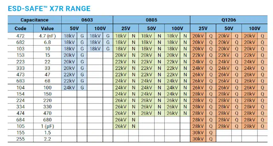
These capacitors contain specialized structures that allow them to tolerate voltage impulses orders of magnitude higher than their continuous DC rating. Examples of X7R devices are shown in table 1. As can be seen, a common 25 V 0805 chip capacitor in this series can withstand 26 kV of ESD.

Table 1 – ESD-Safe MLCC’s from KYOCERA AVX

To understand the protection principle behind using these capacitors, consider the typical ESD test circuit shown in figure 2 for the human body model. Rc, Cd, and Rd are specified by the test standard. Cx is the ESD Safe capacitor added across the device to be protected.

Figure 2 – Human body ESD test model with ESD-safe Cx MLCC ceramic capacitor added for protection
Equation 1 – Final output voltage Vx when protective capacitor Cx is added

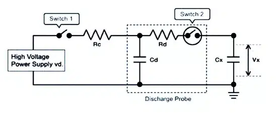
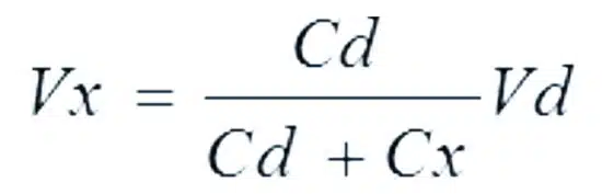
Since Cx is able to safely withstand extremely high ESD voltages, the final voltage (Vx) that will be seen by the downstream circuit will simply be the result of capacitive charge sharing between Cd and Cx. As shown in equation 1, the final output voltage Vx will be significantly reduced by the addition of Cx. If Cx is much larger than Cd, the voltage reduction is substantial.

This simple mechanism provides adequate ESD protection for many I/O lines that are insensitive to the added capacitance. In addition, both cost and space savings are often realized.

Design Considerations for MLCC Protection

Unlike varistors or TVS diodes, there is no clamping voltage or maximum peak voltage defined for the ESD-safe MLCC. Although the use of ESD-safe protection capacitors can be an effective practice, engineers often overestimate the capacitor’s performance by ignoring its inherent degradation with applied voltage. Generally speaking, the amount of capacitance drop for NPO dielectrics is negligible.

However, the amount of capacitance drop for X7R capacitors can be in the 50% range or even greater. Furthermore, the capacitance drop varies from manufacturer to manufacturer and depends on the material composition used for the X7R dielectric. This drop-in capacitance from the expected value of an X7R capacitor can result in a much higher voltage seen by the IC or device to be protected.

As an example, let us consider a 1nF MLCC used in a circuit with the requirement of 8kV contact discharge based on an ESD model capacitor of 150pF. Using an MLCC with NPO dielectric would result in a theoretically calculated voltage of approximately 1044 volts. On the other hand, using a 1nF capacitor with X7R dielectric which has a 50% drop in capacitance the voltage Vx across the capacitor will approach 1846 volts.

One might simply hope to use NP0 capacitors for all their MLCC protection needs. Unfortunately, NP0 MLCCs are limited in their available maximum capacitance value due to the low dielectric constants. For this reason, in many cases, MLCCs with X7R dielectric must be used to provide sufficient ESD protection.

ESD robustness of MLCC

When used for protection against ESD, the MLCC acts as a capacitive voltage divider. The charge of the ESD pulse is distributed among the capacitive layers, and as the number of active electrodes increases, the robustness of the device follows. In addition, increased thickness of each layer helps to improve the voltage that can be withstood.

As such, the generalized rule is that to maximize MLCC robustness for ESD protection, the designer should incorporate the largest possible capacitance in the largest possible case size to achieve the greatest number of total dielectric layers with maximal thickness.

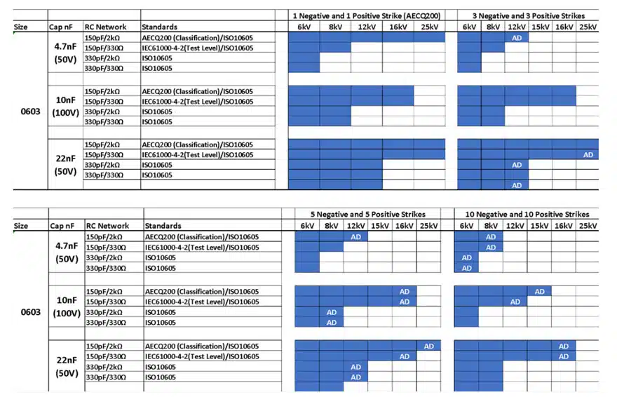
To demonstrate this, KYOCERA AVX carried out ESD robustness tests on a variety of capacitors using the AECQ 200, IEC61000-4-2, and ISO10605 standards. For each run, ten samples of the part were tested. If any single part failed, then the ESD voltage was lowered and ten new parts were tested. Table 2 summarizes these tests for several different 0603 MLCCs, and it is clear that the most robust part is the 22nF device.

Table 2 – ESD Robustness Tests. “AD” stands for “Air Discharge.”

Case Study

The following test setup describes an example ESD test performed on a 0603 ESD-safe MLCC. Not only has the ESD withstand level been measured, but also the maximum peak voltage across the capacitor. An additional load resistor of 33 kOhm has been used in this test setup representing the input impedance of the downstream circuit.

The following equipment and measurements were used for the test:

  • PCB-board: FR4 PCB test board 2 layer, 1.5mm
  • Load resistor: 33kΩ ±1%
  • High voltage probe: P6015A (Tektronix)
  • Oscilloscope (digital): MSO54-5-BW-2000 (Tektronix)
  • 10 strikes (+/-) per unit.

The predetermined pass criteria for the test is:

  • Tested components are within the electrical limits and with no mechanical defects after the tests.

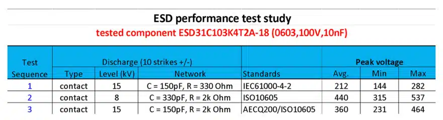
As can be seen in the results in table 3, the MLCC capacitor safely reduces the applied ESD discharge by orders of magnitude. As long as the downstream components are rated to tolerate this reduced voltage, adequate protection can be realized in a simple, small, and cost-effective manner.

Table 3 – ESD-Safe MLCC capacitors performance test results.

Conclusion

MLCC ceramic capacitors offer an inexpensive alternative to protecting I/O lines where speed is not critical. The KYOCERA AVX ESD-Safe™ Series provides a wide range of ESD robust MLCC’s tested according to the AECQ200, IEC61000-4-2, and ISO10605 standards.

In applications where MLCC’s cannot be used, it is recommended to simply use the more traditional Multilayer Varistor (MLV).

Related

Source: KYOCERA AVX

Recent Posts

Samsung Electro-Mechanics Releases High-Capacitance MLCCs for AI Server Applications

21.5.2025
9

Coupled Inductors Circuit Model and Examples of its Applications

21.5.2025
5

Würth Elektronik Introduces LTspice Models for ESD Products

21.5.2025
5

Littelfuse Gate Driver Integrates Diode and Current Limit Resistor in Compact IC

21.5.2025
3

Capacitor Ripple Current Testing: A Design Consideration

21.5.2025
4

Inductor Resonances and its Impact to EMI

16.5.2025
30

Developing Low Inductance Film Capacitor using Bode 100 Analyzer

15.5.2025
40

Würth Elektronik Releases High Performance TLVR Coupled Inductors

15.5.2025
31

Causes of Oscillations in Flyback Converters

15.5.2025
22

YAGEO Extends Rectangular Aluminum Electrolytic Capacitor Family

15.5.2025
49

Upcoming Events

May 28
16:00 - 17:00 CEST

Power Over Data Line

View Calendar

Popular Posts

  • Buck Converter Design and Calculation

    0 shares
    Share 0 Tweet 0
  • What is a Dielectric Constant and DF of Plastic Materials?

    4 shares
    Share 4 Tweet 0
  • Flyback Converter Design and Calculation

    0 shares
    Share 0 Tweet 0
  • Boost Converter Design and Calculation

    0 shares
    Share 0 Tweet 0
  • LLC Resonant Converter Design and Calculation

    0 shares
    Share 0 Tweet 0
  • SEPIC Converter Design and Calculation

    0 shares
    Share 0 Tweet 0
  • How to Design an Inductor

    0 shares
    Share 0 Tweet 0
  • Ripple Current and its Effects on the Performance of Capacitors

    3 shares
    Share 3 Tweet 0
  • DCL Leakage Current Characteristics of Capacitors

    0 shares
    Share 0 Tweet 0
  • Dual Active Bridge (DAB) Topology Explained

    0 shares
    Share 0 Tweet 0

Newsletter Subscription


Passive Components Blog

© EPCI - Leading Passive Components Educational and Information Site

  • Home
  • Privacy Policy
  • EPCI Membership & Advertisement
  • About

No Result
View All Result
  • Home
  • Knowledge Blog
  • Premium Suppliers

© EPCI - Leading Passive Components Educational and Information Site

This website uses cookies. By continuing to use this website you are giving consent to cookies being used. Visit our Privacy and Cookie Policy.
Go to mobile version