Passive Components Blog
No Result
View All Result
  • Home
  • NewsFilter
    • All
    • Aerospace & Defence
    • Antenna
    • Applications
    • Automotive
    • Capacitors
    • Circuit Protection Devices
    • electro-mechanical news
    • Filters
    • Fuses
    • Inductors
    • Industrial
    • Integrated Passives
    • inter-connect news
    • Market & Supply Chain
    • Market Insights
    • Medical
    • Modelling and Simulation
    • New Materials & Supply
    • New Technologies
    • Non-linear Passives
    • Oscillators
    • Passive Sensors News
    • Resistors
    • RF & Microwave
    • Telecommunication
    • Weekly Digest

    Transformer Safety IEC 61558 Standard

    ESR of Capacitors, Measurements and Applications

    Murata Christophe Pottier Appointed President of EPCIA

    3-Phase EMI Filter Design, Simulation, Calculation and Test

    YAGEO Unveils Compact 2.4 GHz SMD Antenna

    KYOCERA AVX Releases Antenna for Iridium Satellite IoT Applications

    Molex Releases Industry-First Quad-Row Board-to-Board Connectors with EMI Shields

    Image credit: Samtec

    How to Match the Right Connector with Protocol Requirements

    Smoltek CNF-MIM Capacitors Pass 1,000h Reliability Test

    Trending Tags

    • Ripple Current
    • RF
    • Leakage Current
    • Tantalum vs Ceramic
    • Snubber
    • Low ESR
    • Feedthrough
    • Derating
    • Dielectric Constant
    • New Products
    • Market Reports
  • VideoFilter
    • All
    • Antenna videos
    • Capacitor videos
    • Circuit Protection Video
    • Filter videos
    • Fuse videos
    • Inductor videos
    • Inter-Connect Video
    • Non-linear passives videos
    • Oscillator videos
    • Passive sensors videos
    • Resistor videos

    Transformer Safety IEC 61558 Standard

    3-Phase EMI Filter Design, Simulation, Calculation and Test

    Transformer Design Optimization for Power Electronics Applications

    Common Mode Chokes Selection for RF Circuits in Next-Generation Communication Systems

    Capacitor Self-balancing in a Flying-Capacitor Buck Converter

    How to Select Ferrite Bead for Filtering in Buck Boost Converter

    Power Inductors Future: Minimal Losses and Compact Designs

    Percolation Phenomenon: Degradation of Molded Power Inductors in DC/DC Converters

    Connector PCB Design Challenges

    Trending Tags

    • Capacitors explained
    • Inductors explained
    • Resistors explained
    • Filters explained
    • Application Video Guidelines
    • EMC
    • New Products
    • Ripple Current
    • Simulation
    • Tantalum vs Ceramic
  • Knowledge Blog
  • Suppliers
    • Who is Who
  • PCNS
    • PCNS 2025
    • PCNS 2023
    • PCNS 2021
    • PCNS 2019
    • PCNS 2017
  • Events
No Result
View All Result
Passive Components Blog
No Result
View All Result

Ferroelectric Materials On Radar Screen for Negative Capacitance

15.12.2022
Reading Time: 7 mins read
A A

Ferroelectric dielectric materials are getting a serious re-examination related to negative capacitance phenomenon, as semiconductor chipmakers look for new options to maintain drive current.

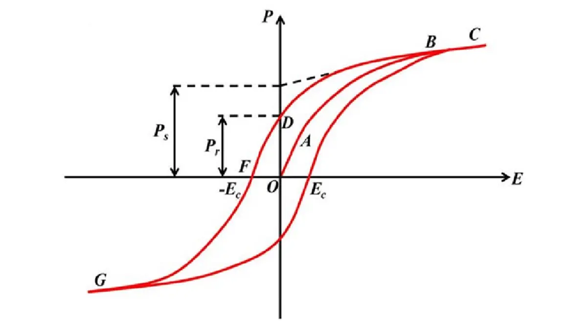
Ferroelectric materials that are commonly used for ceramic class II dielectric capacitors and piezo devices were one of the highlights of the recent IEEE Electron Device Meeting. They are interesting because a built-in electronic dipole creates a remnant polarization, either P+ or P-.

RelatedPosts

Transformer Safety IEC 61558 Standard

ESR of Capacitors, Measurements and Applications

Murata Christophe Pottier Appointed President of EPCIA

Applying a strong electric field — the coercive field, Ec — switches the polarization direction, and the new state persists after the field is removed. Ferroelectric memories rely on this effect for non-volatile data storage.

Ferroelectric transistors are a bit more complicated.

Fig. 1: Ferroelectric polarization as a function of electric field.

They assemble the gate capacitor from a ferroelectric layer (FE) placed in series with a conventional dielectric (DE). Switching the polarization of the FE decreases its charge, leading to a corresponding increase in charge at the DE near the gate. Relative to a conventional MOSFET, this so-called “negative capacitance” effect causes current to increase more rapidly relative to gate voltage, reducing the transistor’s subthreshold swing.

The subthreshold swing (SS), a measure of the steepness of a transistor’s switch from ON to OFF, is the change in voltage needed for a one decade increase in current. As transistors shrink, maintaining an adequate ratio between Ion and Ioff becomes more difficult. A sharper on/off transition is one path to reduced leakage current. Unfortunately, SS in conventional devices is constrained by the Boltzmann limit of about 60mV/decade.

FeFETs have been proposed as a potential solution to this problem. The literature describes these devices as both NCFETs and FeFETs, in part depending on the author’s interpretation of the device physics. (This report uses FeFETs exclusively.) Relative to more radical device architectures, like tunneling FETs, ferroelectric transistors closely resemble conventional MOSFETs. A 2011 demonstration of ferroelectric behavior in hafnium-zirconium oxide (HZO) capacitors showed that ferroelectric materials could be compatible with existing processes. ⁠[1]

What is Negative Capacitance ?
Since the negative capacitance effect was first proposed ⁠[2], though, researchers have been debating its exact nature. Is it simply a transient switching effect, or evidence of a potentially stable third polarization state?

Fig. 2: Free energy versus polarization. Source: K. Derbyshire/Semiconductor Engineering

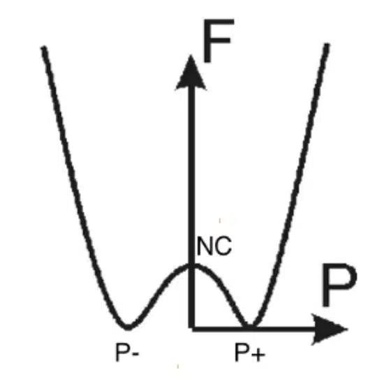
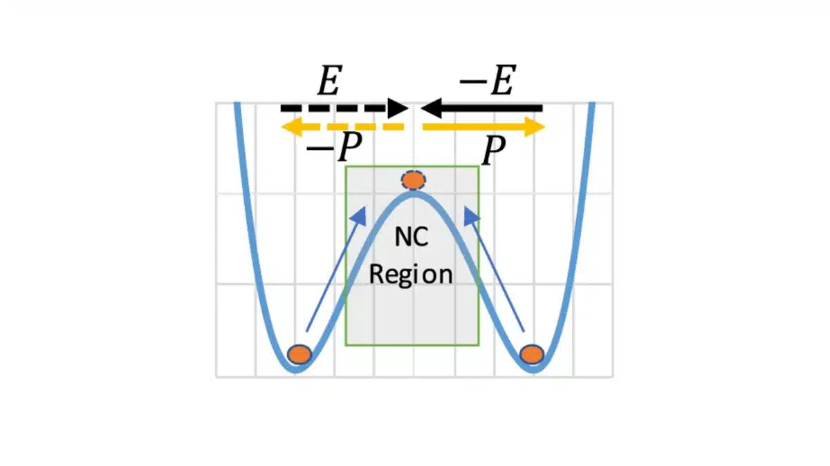
The argument that negative capacitance is a potentially stable state rests on Landau’s analysis [3] of behavior near a phase transition, as illustrated in Figure 2. In between the stable P+ and P- states, this argument holds, there is a “neutral” configuration that can be maintained by interactions with a conventional dielectric. Controlling the negative capacitance effect in transistors requires accurate matching between the FE and DE layers.

The problem with this analysis, according to Jan Van Houdt, imec’s program director for ferroelectrics, is that the transition between the P+ and P- states corresponds to physical movement of ions in the ferroelectric unit cell. A chemical bond breaks and re-forms; there is no stable state intermediate between the two. Moreover, figure 2 is derived from the Landau-Devonshire model for steady state behavior in equilibrium conditions. Using an equilibrium model to describe switching behavior is inherently problematic.

Instead, discussions of switching dynamics need to consider the forces acting on the material. In the absence of an external field, each ferroelectric unit cell is an electronic dipole surrounded by other dipoles.[⁠4] In a single crystal the lowest energy state will be one in which all of the dipoles are aligned in the same direction. In HZO deposited on HfO2 or silicon, a more likely result is a polycrystalline material, with grain boundaries and somewhat random crystal orientations. The P+ direction for one grain may not align with the P+ direction of its neighbors. Depending on the deposition conditions, there may even be crystallites that are not ferroelectric at all. ⁠[5] The net polarization of the material is the sum of the P+ and P- domains.

When an electric field is applied, the dipoles begin to align themselves with it. Switching of individual dipoles is very fast — one of the fastest electronic switching mechanisms known — but not all domains in a multi-crystalline, randomly oriented film will switch at once. Shifting the net polarization from P+ to P- or vice versa requires finite time.

Read more about negative capacitance in post here: Negative Capacitance in Action

Optimizing subthreshold swing
While the switching is taking place, the change in polarization leads to a change in the net capacitance of the material. Maintaining a constant voltage requires an influx of charge from an external source: current flows. Huimin Wang and colleagues at Peking University explained that negative capacitance behavior thus occurs when the rate of change of the polarization is greater than the rate of change of the capacitance. ⁠[6] They observed the effect in standalone FE capacitors, indicating that the presence of a DE layer is not fundamental to the effect. When a ferroelectric is in series with a conventional dielectric, though, the interaction between the two will define the overall electrostatics of the device.

Fig.3 (a) Creation of depolarization field in ferroelectric-dielectric stack, (b) depolarization field acts as a stabilization mechanism of the negative capacitance in the ferroelectric, (c) a method of obtaining depolarization field by controlling the surface charge density. Source [4]

Even if there is no persistent negative capacitance state, it is possible to have negative differential capacitance. Depending on the sweep rate of the gate voltage, the net capacitance may increase sharply, then fall as the gate voltage “catches up” and Vth is reached.

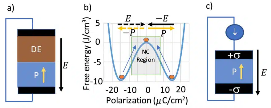
Negative capacitance (NC) can be stabilized by putting a non-ferroelectric capacitor in series with the FE. When the voltage across the stack is zero as shown in Fig. 2(a), the negative sign indicates that the electric field acts against the polarization. Such field is called the depolarization field. Depolarization field pushes the polarization state from the minima towards the top of the Landau free energy landscape. Consequently it acts as a stabilization mechanism that keeps the FE in the NC region as shown in Fig. 2(b). Note that this is not the only way to establish a depolarization field. The electric field inside a FE arises from the surface charge density σσ supplied from an external source as shown in Fig. 2(c).

Whether ferroelectric behavior is relevant for commercial devices therefore remains an open question.

For memory, (to be discussed in Part II of this series), the answer seems to be unequivocally, yes. Rapid, persistent switching places FeRAM in an important niche between flash memory and DRAM. For transistors, though, the answer is less clear. While using negative capacitance to enhance MOSFET performance may not be possible, some 2D semiconductor materials also have ferroelectric characteristics. Part III in this series will consider what role ferroelectrics might play in advanced channel devices.

References

  • 1. J. Müller, et. al., “Ferroelectric Zr0.5Hf0.5O2 thin films for nonvolatile memory applications”, Appl. Phys. Lett. 99, 112901 (2011) https://doi.org/10.1063/1.3636417
  • 2. Sayeef Salahuddin and Supriyo Datta, “Use of Negative Capacitance to Provide Voltage Amplification for Low Power Nanoscale Devices”, Nano Letters 2008 8 (2), 405-410 DOI: 10.1021/nl071804g
  • 3. P. Chandra and P.B. Littlewood, “A Landau Primer for Ferroelectrics.” https://doi.org/10.48550/arXiv.cond-mat/0609347
  • 4. Alam, M.N.K., Roussel, P., Heyns, M. et al. “Positive non-linear capacitance: the origin of the steep subthreshold-slope in ferroelectric FETs.” Sci Rep 9, 14957 (2019). https://doi.org/10.1038/s41598-019-51237-2
  • 5. M. Dragoman, et. al., “The Rise of Ferroelectricity at Nanoscale: Nanoelectronics is rediscovering the ferroelectricity,” in IEEE Nanotechnology Magazine, vol. 15, no. 5, pp. 8-19, Oct. 2021, doi: 10.1109/MNANO.2021.3098217.
  • 6. H. Wang et al., “New Insights into the Physical Origin of Negative Capacitance and Hysteresis in NCFETs,” 2018 IEEE International Electron Devices Meeting (IEDM), 2018, pp. 31.1.1-31.1.4, doi: 10.1109/IEDM.2018.8614504.

Related

Source: Semiconductor Engineering

Recent Posts

ESR of Capacitors, Measurements and Applications

7.11.2025
10

3-Phase EMI Filter Design, Simulation, Calculation and Test

6.11.2025
23

Smoltek CNF-MIM Capacitors Pass 1,000h Reliability Test

6.11.2025
9

Capacitor Lead Times: October 2025

6.11.2025
50

Paumanok Unveils Aluminum Capacitor Foils World Markets Study 2025-2030

6.11.2025
13

Microhardness — the Hidden Key to Understanding MnOx Cathode Quality in Tantalum Capacitors

3.11.2025
23

Samsung to Invest in its Philippine MLCC Facility to Meet Automotive Demand

3.11.2025
31

Lightweight Model for MLCC Appearance Defect Detection

3.11.2025
25

DMASS Reports First Positive Signs of European Distribution Market in Q3/25

3.11.2025
13

TAIYO YUDEN Releases 22uF MLCC in 0402 Size for AI Servers

3.11.2025
16

Upcoming Events

Nov 11
17:00 - 18:00 CET

Industrial Applications Demand More from Interconnects in Next-Gen Designs

Nov 12
11:00 - 12:00 CET

PCB Design: Impedance is for everyone!

Nov 12
November 12 @ 12:00 - November 13 @ 14:15 EST

Microelectronic Packaging Failure Modes and Analysis

View Calendar

Popular Posts

  • Buck Converter Design and Calculation

    0 shares
    Share 0 Tweet 0
  • Boost Converter Design and Calculation

    0 shares
    Share 0 Tweet 0
  • LLC Resonant Converter Design and Calculation

    0 shares
    Share 0 Tweet 0
  • Flyback Converter Design and Calculation

    0 shares
    Share 0 Tweet 0
  • Ripple Current and its Effects on the Performance of Capacitors

    3 shares
    Share 3 Tweet 0
  • MLCC and Ceramic Capacitors

    0 shares
    Share 0 Tweet 0
  • Dual Active Bridge (DAB) Topology

    0 shares
    Share 0 Tweet 0
  • What is a Dielectric Constant and DF of Plastic Materials?

    4 shares
    Share 4 Tweet 0
  • SEPIC Converter Design and Calculation

    0 shares
    Share 0 Tweet 0
  • Flying Capacitors

    0 shares
    Share 0 Tweet 0

Newsletter Subscription


Passive Components Blog

© EPCI - Leading Passive Components Educational and Information Site

  • Home
  • Privacy Policy
  • EPCI Membership & Advertisement
  • About

No Result
View All Result
  • Home
  • Knowledge Blog
  • PCNS

© EPCI - Leading Passive Components Educational and Information Site

This website uses cookies. By continuing to use this website you are giving consent to cookies being used. Visit our Privacy and Cookie Policy.
Go to mobile version