


The article explains construction, application and features of film and foil organic dielectric capacitors:
- Paper MP capacitors
- Polyester PET /KT/MKT capacitors
- Polypropylene PP /KP/MKP capacitors
- Polycarbonate PC /KC/MKC capacitors
- Polystyrene PS, Polyphenylene sulfide PPS and other plastic film capacitors Teflon PTFE / Polysulfone PSU
Film capacitors are essential electrostatic capacitors suitable for medium, higher voltage and higher current circuits. Unlike most other dielectric systems, film capacitors feature low loss factor at very low temperature.
Dielectric constant is not big, but they feature very high dielectric strength. In combination with long life and self-healing aging capabilities it makes them ideal choice for high voltage, high power systems. While we focus on the most common dielectric types there is a wide list of organic dielectric materials with different features. Overview can be seen in the article: What is a Dielectric Constant of Plastic Materials ?
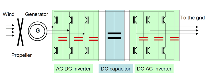
Due to its high dielectric strength, film capacitors are often used in high-power, high-voltage applications including modern resonant power converters in renewable energy or EV charging circuits. Its ripple current capabilities can be further improved by cooling – learn more in the video here: Water Cooled Polypropylene Capacitors
Introduction & Benchmarking
There are more types of film capacitors that differs by structure of the electrodes (if metal film electrode is used or metallization is already deposited on the electrodes) and type of dielectric as illustrated in the Figure below.
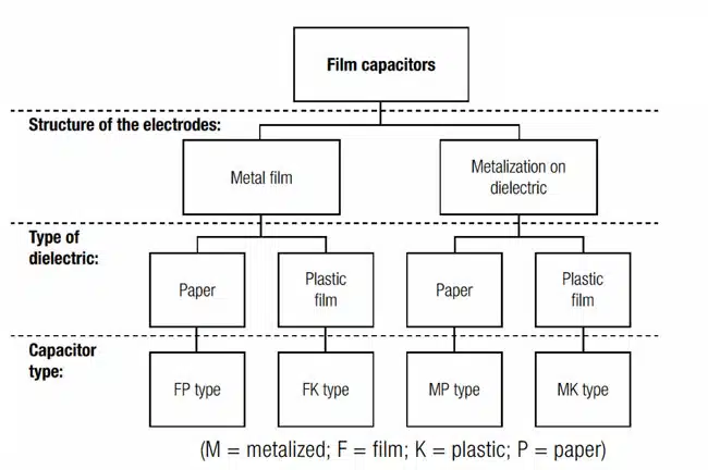
The most common dielectric materials used in the construction of plastic film capacitors are polypropylene and polyester. Other dielectrics used in the construction of film capacitors include polycarbonate, polystyrene, polytetrafluoroethylene (PTFE), polyethylene naphthalate (PEN), polyphenylene sulphide (PPS), polyimide, and paper as discussed in next chapters in more details. The following table shows common codes for the main dielectric types:
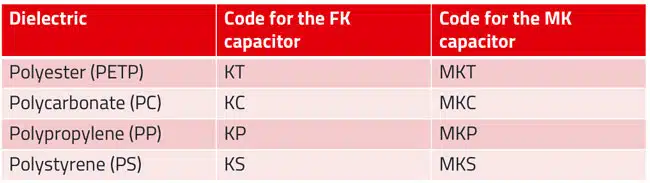
Polyester (PET)
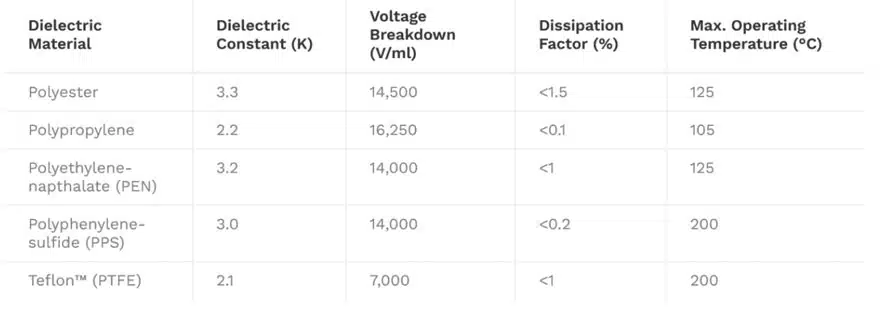
Polyester has a high dielectric constant compared to polypropylene, and is one of the most widely used dielectric materials. This high dielectric constant allows construction of capacitors with small physical sizes. Polyester capacitors, also known as mylar capacitors, have good self-healing properties and are relatively cheap.
At high temperatures, polyester capacitors dissipate more power. This characteristic makes these capacitors unsuitable for high frequency and high current AC applications. Furthermore, polyester exhibits a significant capacitance change, up to 5%, as temperature approaches low or high-temperature limits. Due to this characteristic, polyester is an unsuitable material for constructing precision capacitors. Polyester capacitors are mostly used in general purpose board level applications such as blocking, bypassing, decoupling, and some noise suppression circuits.
Polypropylene (PP)
Polypropylene is commonly used in the construction of capacitors for high frequency AC applications. This dielectric material has a low dissipation factor, high breakdown strength, low dielectric absorption, high insulation resistance, and is readily available. These properties make polypropylene a dielectric material of choice for a wide range of applications including snubber circuits, high frequency AC systems, high voltage DC & AC systems, and high current DC applications.
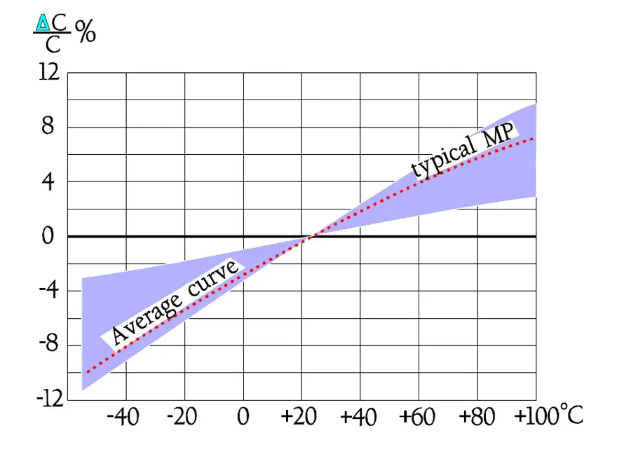
Polypropylene capacitors can operate over a wide temperature range. Unlike polyester capacitors, the capacitance of a polypropylene capacitor decreases with temperature. Due to its temperature characteristics, polypropylene capacitors are commonly used to complement polyester capacitors. This is achieved by connecting a polyester capacitor and a polypropylene capacitor in parallel.
Despite its impressive properties, polypropylene has a lower dielectric constant than polyester. In addition, this material is not available in thin-gauge films. Compared to polyester, polypropylene is more expensive and is not a suitable material when physical size of a component is a key consideration.
Polyphenylene sulphide (PPS)
Polyphenylene sulphide has excellent temperature characteristics and is commonly used for constructing precision capacitors. The capacitance of these capacitors does not vary significantly with changes in temperature. PPS capacitors are commonly used to replace polycarbonate capacitors in electronic circuits. The dielectric constants of these two materials are similar, and both have high breakdown strength.
Polytetrafluoroethylene (PTFE)
PTFE capacitors, also known as Teflon capacitors, are low loss capacitors that offer excellent stability. PTFE has a relatively low dielectric constant, around 2.1, and it is, therefore, unsuitable for constructing components with small footprints. Teflon capacitors are suitable for high temperature applications and can be used in systems that expose components to temperatures of up to 200oC. PTFE capacitors have low capacitance values and are relatively expensive.
Polystyrene (PS)
Polystyrene capacitors exhibit extremely low loss and high capacitance stability over temperature, typically down to ±1% 0ver the range -55°C to +85°C. It’s low dielectric constant of 2.1 makes in suitable for low capacitance, high stability applications such as timing circuits.
Polyimide (Kapton)
Polyimide has a high dielectric constant, around 3.4, and it is commonly used for constructing components for high temperature applications. Kapton capacitors can be used in systems that can expose components to temperatures of up to 250oC. Metallized polyimide capacitors have poor self-healing characteristics.
Polycarbonate (PC)
Polycarbonate has an average dielectric constant, around 2.7, and it is commonly used in the construction of capacitors for high temperature applications. Polycarbonate capacitors are low loss components that have good electrical characteristics over a wide temperature range. Polycarbonate capacitors were widely used in military applications. However, polycarbonate film has limited availability, and is not recommended for new designs.
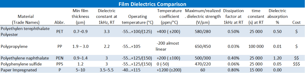
The table below summarises some characteristics of common plastic film dielectrics.
Applications & Designs
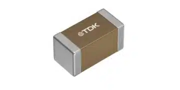
There are various forms of film capacitors on market from SMD chip style up to high power high voltage types:
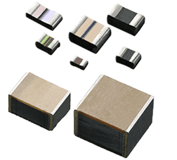
SMD Stacked Chip
0.01uF – 15uF
30 – 400V
up to 125°C
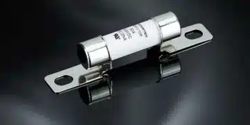
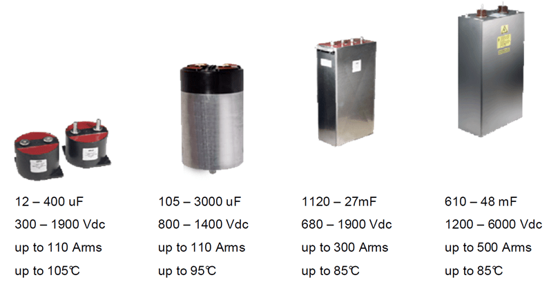
Medium Power
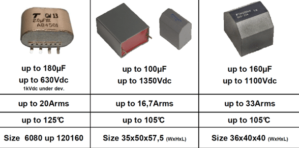
High Power
Some typical examples of film capacitor applications:
- DC link in automotive or renewable energy generators
- AC motor and light start
- Medical defibrilators
- Railway systems
- Defence and space hardware
- Energy distribution and power correction
- X and Y safety capacitors
- EMI noise suppression
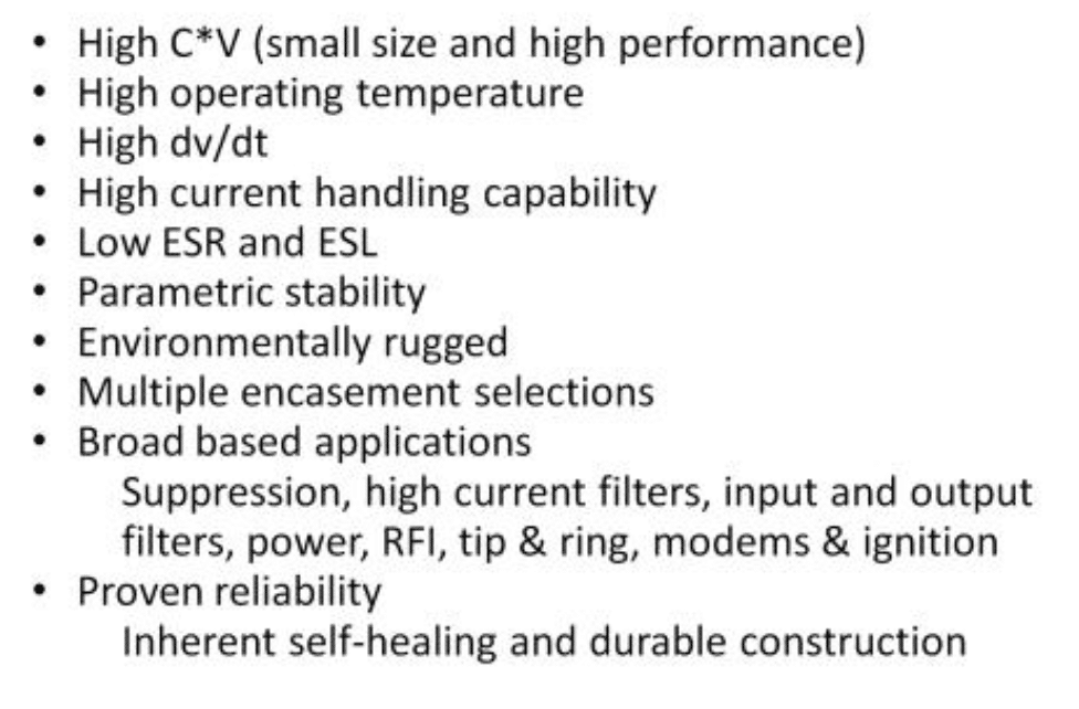
Key Attributes of Film Capacitors:
Polar Plastics Vs Non-polar Plastic Dielectrics
Dielectric properties of a polymer largely depend upon their structure. The structure determines whether a polymer is polar or non-polar and this in turn decided the electrical properties of the polymer.
- In polar polymers (PMMA, PVC, Nylon, PC etc.), dipoles are created due to imbalance in the distribution of electrons. These dipoles tend to align in the presence of electric field. Hence, this creates dipole polarization of the material making these materials only moderately good as insulators.
- While non-polar polymers (PTFE, PP, PE, PS) have symmetrical molecules and are truly covalent. There are no polar dipoles present in them and hence in presence of electric field does not align the dipoles. However, slight electron polarization occurs due to the movement of electrons in the direction of electric field, which is effectively instantaneous. These polymers have high resistivities and low dielectric constant.
Polar plastics have a tendency to absorb moisture from the atmosphere. Presence of moisture raises the dielectric constant and lowers the resistivity. With rise in temperature, there is faster movement of polymer chains and fast alignment of dipoles. This invariably raises the dielectric constant values for polar plastics.
Non-polar plastics are not affected by moisture and rise in temperature. Dielectric constant of various plastic materials can be found in the post linked in material folder of this lesson.
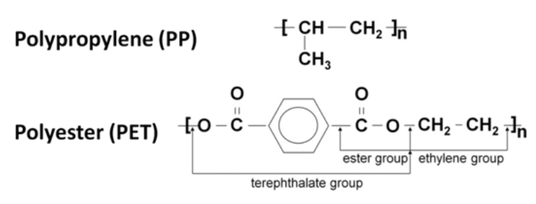
PET and PP totally dominate the film capacitor dielectric market. PP is a small and simple molecule. PET is „heavier” but also provides a stronger and higher tensile strength film that con be bi-axially oriented into very thin films.
Film Capacitor Construction and Manufacturing
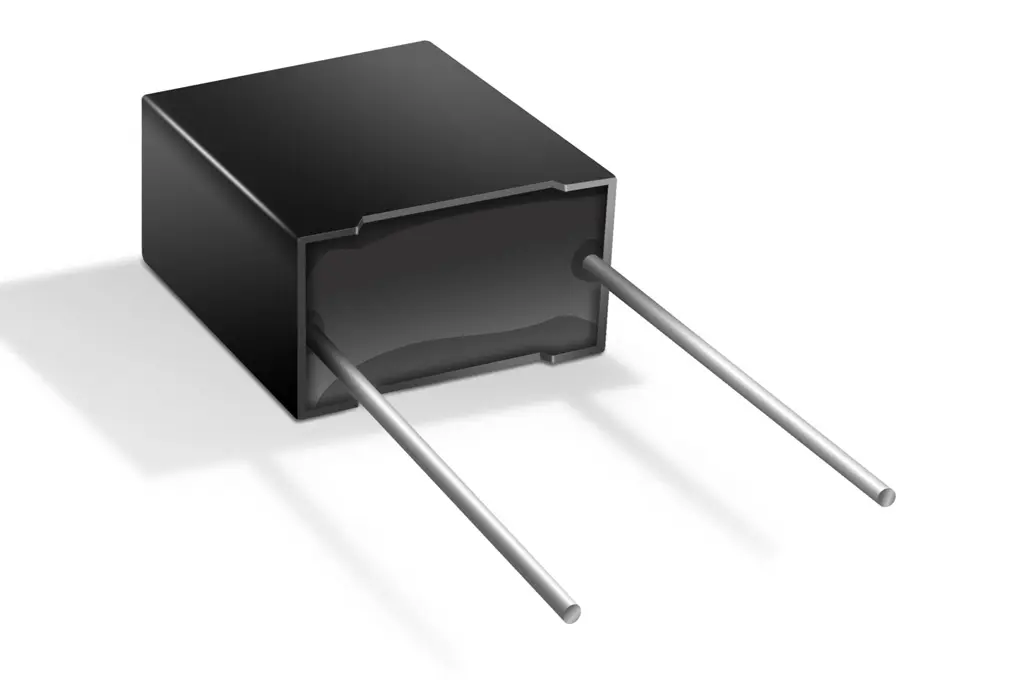
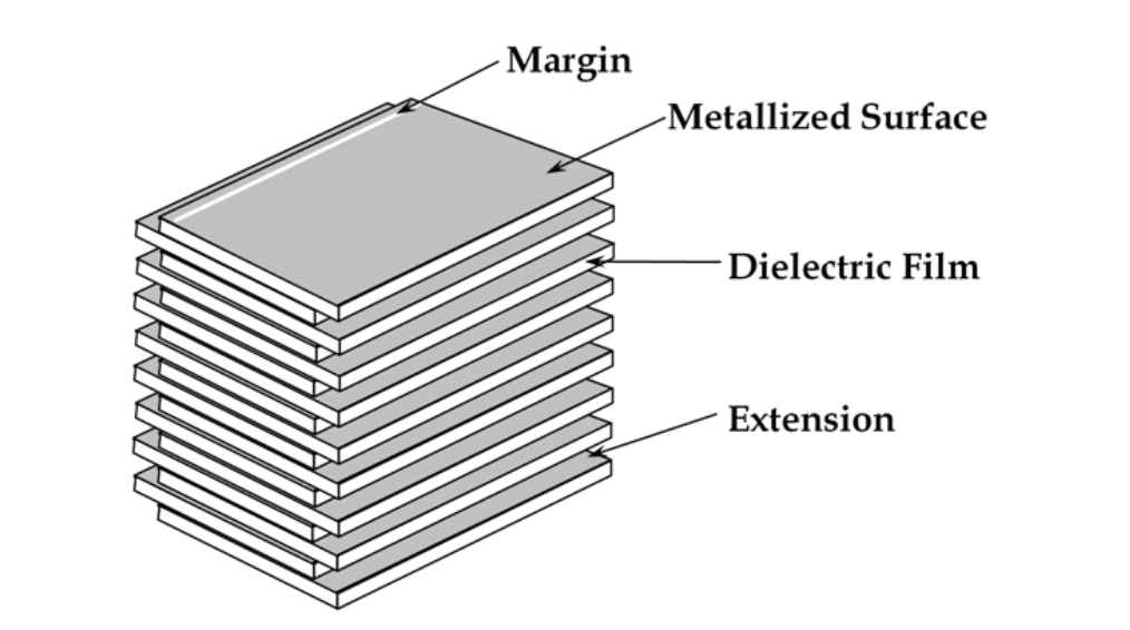
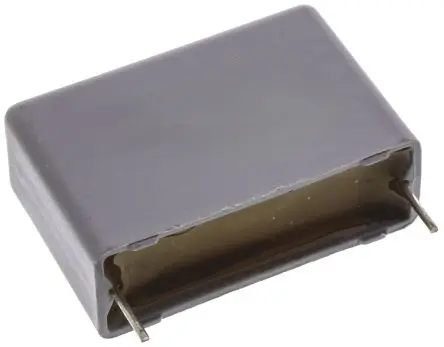
Film capacitors can be produced as wound or stacked foil capacitors types depending to the final application requirements and features – see figures bellow. Minimum rated voltage of film capacitors is mostly limited by its mechanical strength to withstand the winding process and it starts typically from >3um per layer corresponding to ~30V, thus it is not direct competition to low voltage SMD other capacitor technologies.
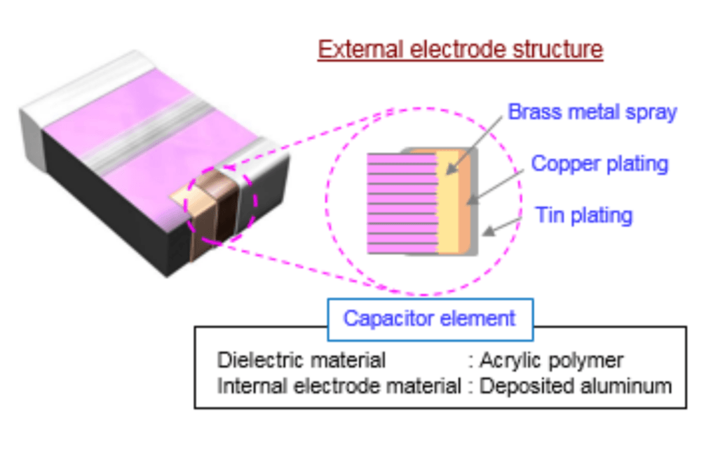
The exception is multilayer SMD stacked capacitor Rubycon PMLCAP(R) that employs electron beam curing resin as the dielectric material and vacuum deposition polymerization technology as manufacturing method that enable dielectric thickness to be less than 1um allowing minimum voltage (and high capacitance) from 10/16V and offer alternative to MLCC class I capacitors even at low voltage applications.
Construction
Manufacturing Process
The following example describes a typical manufacturing process flow for wound metallized plastic film capacitors.
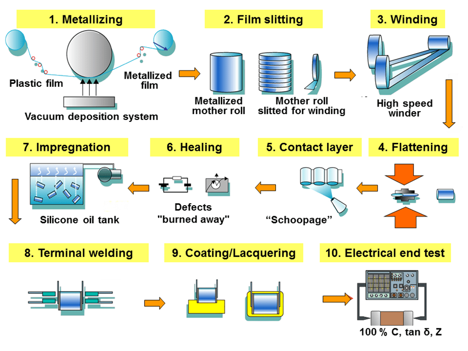
- Film stretching and metallization — To increase the capacitance value of the capacitor, the plastic film is drawn using a special extrusion process of bi-axial stretching in longitudinal and transverse directions, as thin as is technically possible and as allowed by the desired breakdown voltage. The thickness of these films can be as little as 0.6 μm. In a suitable evaporation system and under high vacuum conditions (about 1015 to 1019 molecules of air per cubic meter) the plastic film is metallized with aluminum or zinc. It is then wound onto a so-called “mother roll” with a width of about 1 meter.
- Film slitting — Next, the mother rolls are slit into small strips of plastic film in the required width according to the size of the capacitors being manufactured.
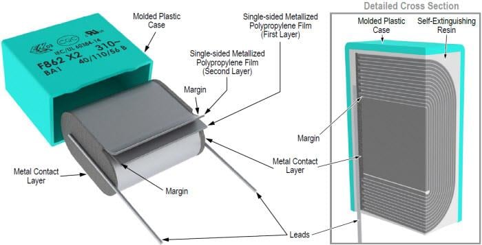
- Winding — Two films are rolled together into a cylindrical winding. The two metallized films that make up a capacitor are wound slightly offset from each other, so that by the arrangement of the electrodes one edge of the metallization on each end of the winding extends out laterally.
- Flattening — The winding is usually flattened into an oval shape by applying mechanical pressure. Because the cost of a printed circuit board is calculated per square millimeter, a smaller capacitor footprint reduces the overall cost of the circuit.
- Application of metallic contact layer (“schoopage”) — The projecting end electrodes are covered with a liquefied contact metal such as (tin, zinc or aluminum), which is sprayed with compressed air on both lateral ends of the winding. This metallizing process is named schoopage after Swiss engineer Max Schoop, who invented a combustion spray application for tin and lead.
- Healing — The windings which are now electrically connected by the schoopage have to be “healed”. This is done by applying a precisely calibrated voltage across the electrodes of the winding so that any existing defects will be “burned away” (see also “self-healing” below).
- Impregnation — For increased protection of the capacitor against environmental influences, especially moisture, the winding is impregnated with an insulating fluid, such as silicone oil.
- Attachment of terminals — The terminals of the capacitor are soldered or welded on the end metal contact layers of the schoopage.
- Coating — After attaching the terminals, the capacitor body is potted into an external casing, or is dipped into a protective coating. For lowest production costs some film capacitors can be used “naked”, without further coating of the winding.
- Electrical final test — All capacitors (100%) should be tested for the most important electrical parameters, capacitance (C), dissipation factor (tan δ) and impedance (Z).
Paper Capacitors
Under this headline we deal mainly with pure paper dielectrics. At the same time we ought to say that combinations of paper and plastic, i.e. mixed dielectrics, are rather common.
The “pure” paper capacitors (MP) are not anymore in often use, but it is good to get familiar with the technology and explain some principles. Metallized paper MP and plastic film MK (MKP and MKT) technologies are still used today as EMI noise suppression capacitors.
Plastic film MKT and MKP electrostatic capacitors are offering higher capacitance values in smaller case sizes compared to MP capacitors. However, thanks to the good oxidation behaviour of the paper dielectric, MP paper capacitors have outstanding self-healing properties and reliability even with high energy pulses.
Paper / foil
The history of the commercial capacitor started with paper foil dielectrics and electrodes of aluminum foils. Because paper is porous it has to be impregnated in order to prevent corona effects and flash-overs. It is done by use of melted wax or different kinds of oils, among other things mineral and silicone oils. The oils increase the tensional stability but decrease to a certain extent the εr. Fibrous paper has an εr ≈ 6.6 and the mineral oil ≈ 2.3 which gives the impregnated winding an εr varying between 3.1 and 4.5. The differences depend above all on the winding pressure produced by the tensile force during winding.
Formerly at least two impregnated paper foils were used because of the character of the paper. Today mixed dielectrics are used frequently where the paper is combined with plastic foils, usually polyester (PET) or polypropylene.
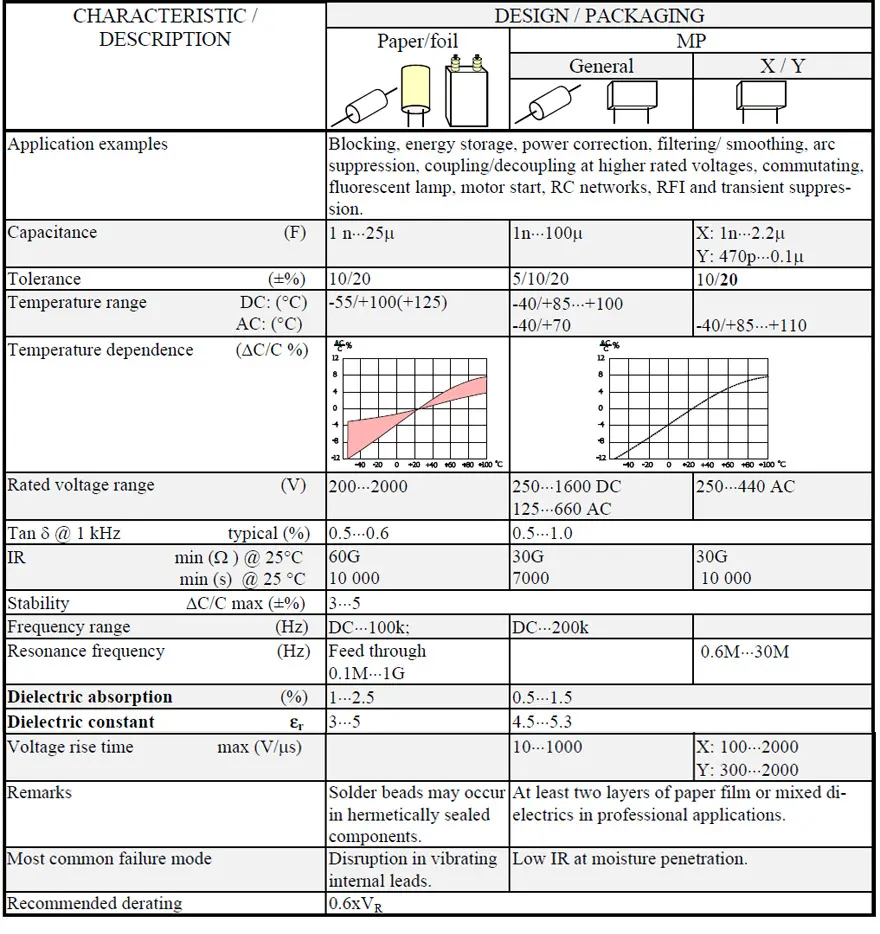
Because the summary tables following each presented material type don’t deal with the impregnation agents and mixed dielectrics separately we mention some of their characteristics in following Table 1.
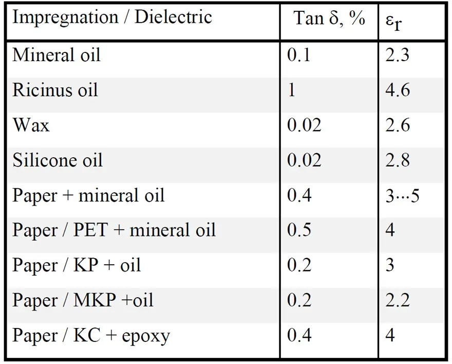
Oil impregnated paper is, above all, used in power, mains and in certain feed-through capacitors. In this handbook we restrict ourselves to those smaller types which belong to the electronic components. They constitute an fading component category that more and more is replaced with plastic dielectrics.
In common mains and feed-through capacitors intended for consumer purposes the casings contain only a faint amount of oil. Most of it exist in the paper foils. The impregnation is carried out in vacuum on the finished winding after that the paper first has been dried carefully in an oven.
MP (metallized paper)
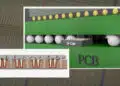
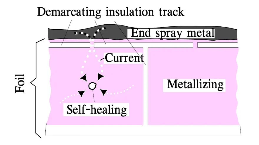
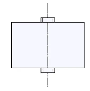
The first metallized film capacitor was built with metallized paper. The MP foil looks in principle like the one in Figure 1.
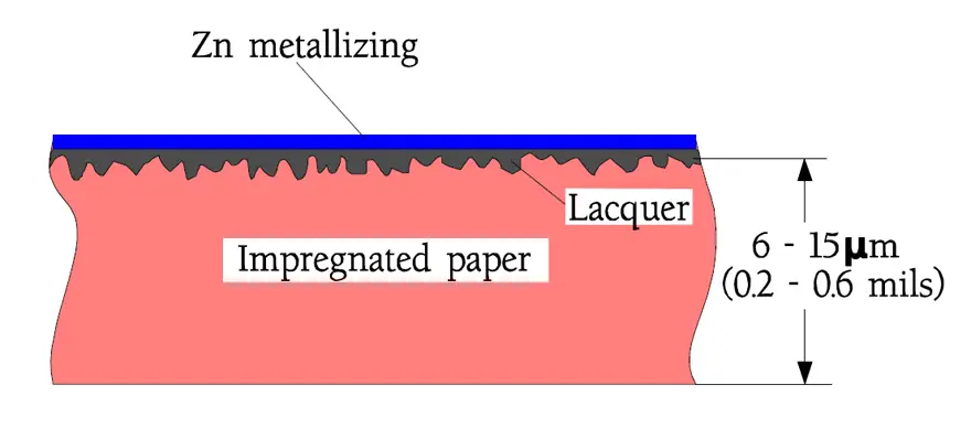
As impregnation agents solid substances like epoxy is predominant but vegetable oils may occur in certain types. The impregnation also protects the zinc metallization against aqueous corrosion and oxidation. Because the paper is porous and in certain points may contain some impurities or weaknesses one must in professional applications use designs with at least two layers of paper foils. The risk that a weak spot in one foil shall land opposite another one in the next layer is minimized. In stead of an extra paper foil nowadays mixed dielectrics are more and more frequently used with a polyester or polypropylene film together with the metallized paper foil. Also occurring are variants with a metallized plastic film and an impregnated paper foil.
The genuine MP capacitor once was falling out of use but concurrently with experiences from the plastic films it has witnessed a well-motivated renaissance. Above all it has to do with the need for transient protecting capacitors in mains applications. According to Table C2-1 the carbon deposit from self-healings produced during manufacture – so called clearings – are uniquely low for cellulose materials at the same time as the necessary energy release stops at completely harmless levels (ΔV ≈ -10 mV… -1 V).
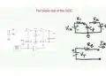
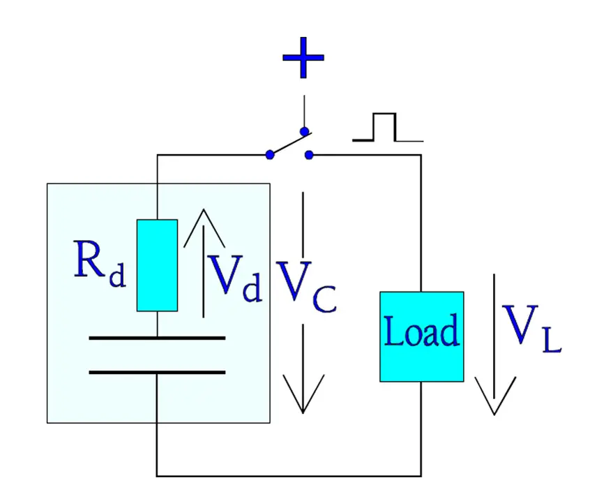
Besides the MP capacitor has another advantage at pulse applications. Pulses mean steep voltage rise times and high charge and discharge currents. The usual zinc metallization together with an end spray metal consisting of a zinc compound (shooping metal) gives just that low ESR in the contact interface that is necessary for avoiding a local heating. Repetitive courses of pulse events may on the other hand create internal heating because of the dielectric losses. If the capacitor is used as an energy storing pulse transmitter part of the energy will be lost in the dielectric loss resistance Rd. The voltage Vc of the charged capacitor will at the discharge be voltage divided in Vd and VL (Figure 2.).
Transient Suppression / X- and Y- Safety Capacitors
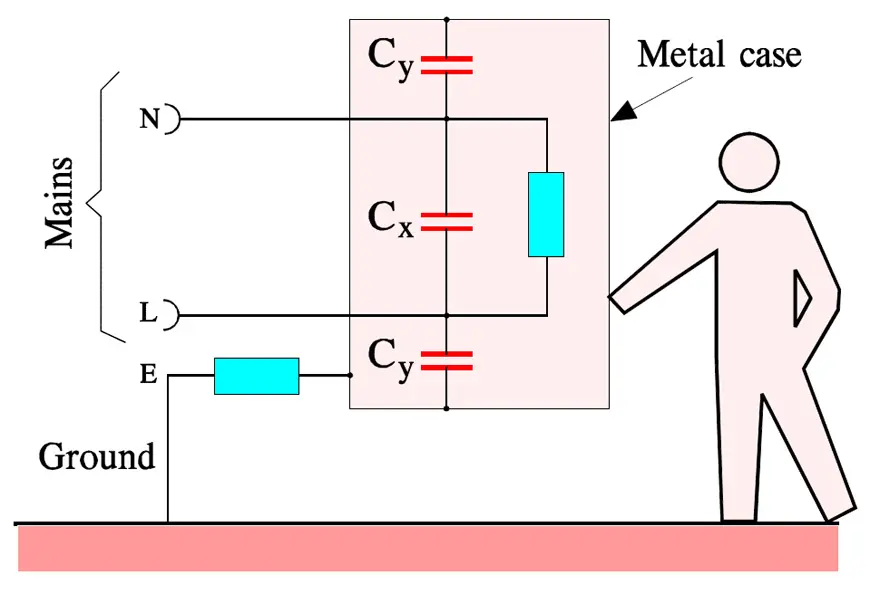
In the group of RFI capacitors that shall protect against Radio Frequency Interference so called X- and Y-capacitors are included. They are connected to the mains according to Figure 3. There they also serve another important purpose. Transients strike namely every live mains relatively often. They may come from the ”outside” but may also be generated by our own equipment.
Between 80 and 90 % of all transients from the mains last between 1 and 10 μs, are higher than 1000 V, have voltage rise times of 200 to 2000 V/μs and are occurring at least 10 times a day. We realize that their damage must be eliminated. It is done by the X-capacitors which thus are connected between the lines of the mains.
The Y-capacitors represent another type of transient suppression. They are connected between either of the power lines and the grounded cover of electric equipment. Here we require an extra high safety against short-circuits in order to prevent the equipment being put under tension and thus causing serious personal injuries. Besides, the Y-capacitor shall have a limited capacitance in order not to bring about harmfully high currents through the human body in case of a possible open circuit in the ground wire (see Figure 3.).
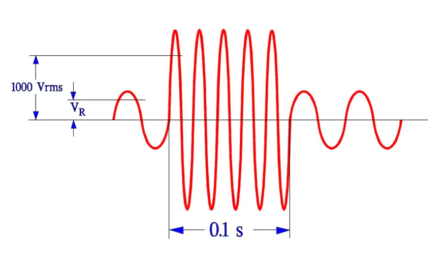
In order to verify that the X- and Y-capacitors really can withstand occurring transients they must pass the following three tests without remarks.
- Life test according to IEC 384-14, 1000 hrs at Tuc and 1.25xVR + 1000 Vrms every hour for 0.1 s.
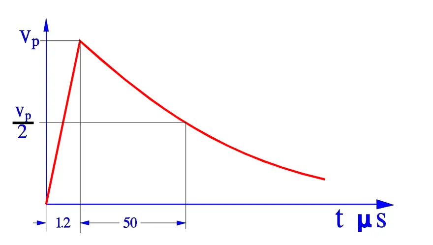
- Surge voltage test according to 384-14. Three pulses of Vp = 2.5 to 5 kV depending on capacitor type.
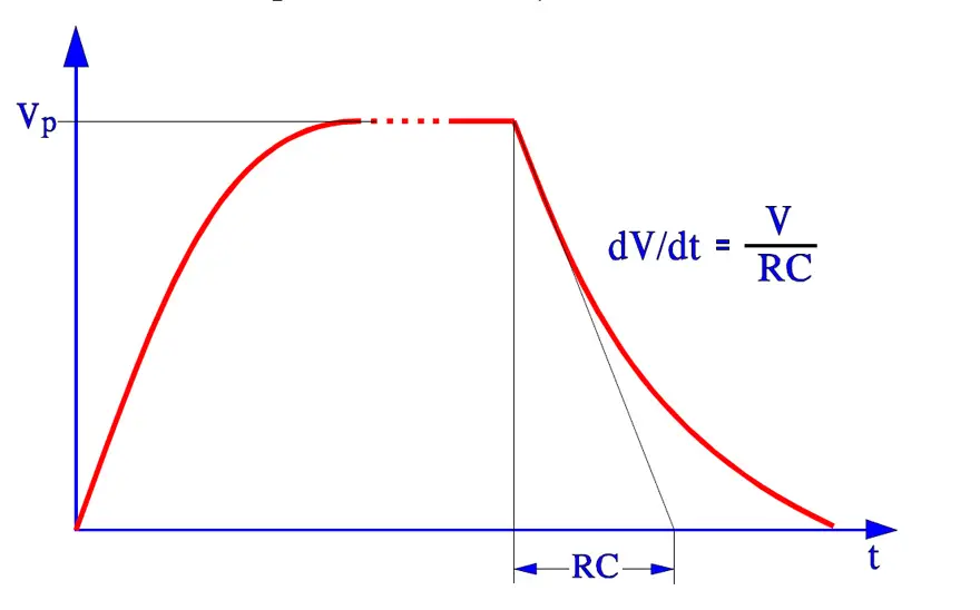
- Charge and discharge test according to IEC 384-14. 10 000 pulses at 100 V/s and 2xVR.
X- and Y-capacitors must have an approval by national inspection authorities in order to be used in respective countries. All European check routines are collected in one standard, EN 13 24 00. The USA standards are collected under UL and the Canadian under CSA.
MP or MK?
In X- and Y-capacitor applications we have to count on self-healing breakdowns. The voltage drop caused by a self-healing depends on the energy that is consumed in order to evaporate dielectric and metallizing. Here MPs with their zinc metallizing have been superior to plastic film capacitors which by tradition have had an Al metallization whose evaporation process requires several times higher energy than Zn. Nowadays, however, plastic film capacitors (MK) are brought on the market with metallization alloys based on the advantageous characteristics of zinc but without its tendency towards aqueous corrosion.
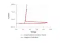
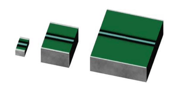
Further on there exist special designs of metallized plastic films where a segmented metallization is used, sometimes called a structure metallization. The surface is divided in mutually demarcated elements that are within reach of the charging current via narrow gates. At a self-healing the surge current burns them off. See example in Figure 7. and 8. below. The surface element is isolated and the discharge current from other elements is cut off as well as the beginning voltage drop. One gets approximately the same energy limitation as by a self-healing in an MP capacitor, especially if the structure metallization is combined with choices of modern metallizing alloys. Following Figure 7. shows typical self-healing effects on the voltage drop over a capacitor.
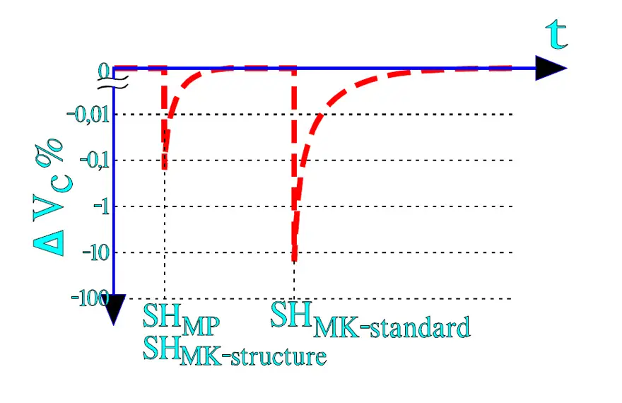
The metallized plastic films (MK) that hitherto have been used are polyester (MKT) and polypropylene (MKP). The latter need not be structure metallized due to its excellent self-healing chemistry. Combined with very thin ZnAl metallizing the design gets the same characteristics as structure metallized MK. In addition its high frequency characteristics are superior to those of other films.
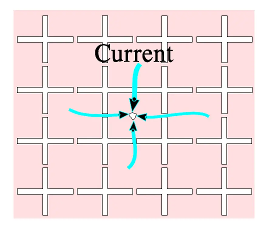
The metallizing in structured surface elements makes great demands for the design. Even if cost-effective methods are developed they involve a certain rise in prices. The simplified segmented metallization in Figure 8. actually consists of a grid-like pattern that is distributed over the whole surface as shown in Figure 9.
Another, and very interesting, structure metallization consists of metallized circular surfaces on top of a thin, high surface resistivity metallizing that covers the total surface. The weak circular joints serve together with the thin underlying metallization as fusing elements. The fusing function is favored by a metallization of zinc or low energy alloy.

Every self-healing reduces the capacitance correspondingly to the surface reduction. The author’s opinion is that the MP capacitor still is superior to structure metallized MK types. But, of course, both types meet current standards and safety requirements.
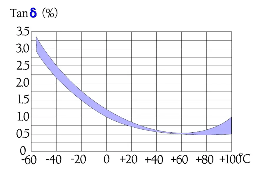
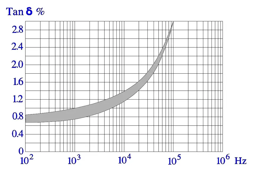
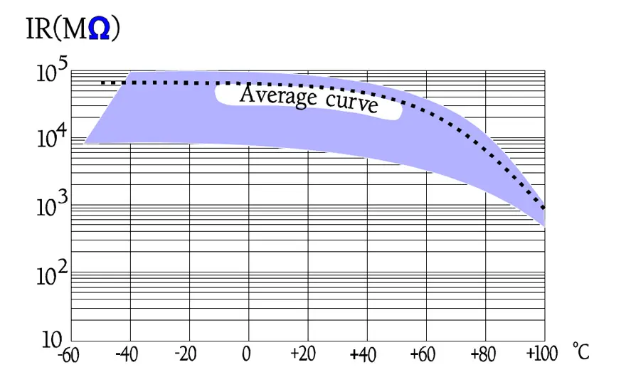
Temperature and frequency dependencies
Following diagrams show some typical graphs for the temperature and frequency dependence of paper capacitors.
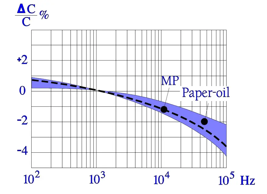
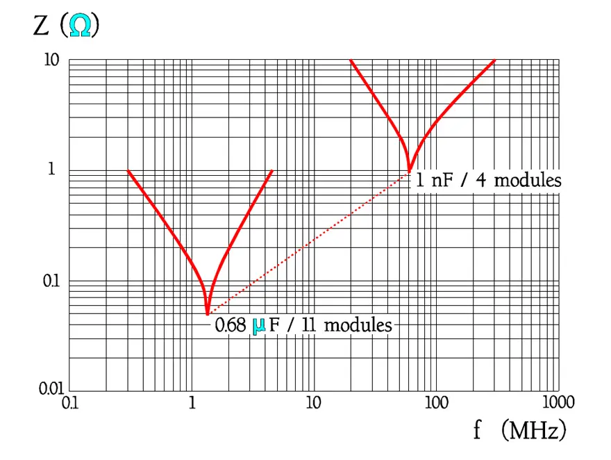
In Figure 16., the impedance curve turns down in a sharp point around the resonance frequency. In low-loss components like film capacitors the decreasing capacitive reactance curve reach areas around the resonance frequency before it get to the limiting ESR contribution. Here the reactance drops even faster than according to the initial curve because of the counteracting inductive reactance.
The tip of the impedance curve in Figure 16. is in a larger magnification not so sharp that is indicated in the diagram.
(In capacitors with rather high losses as, for example, electrolytics the reactance curves reach the ESR contribution at frequencies far away from the resonance frequency. Here produces the dipole dependent capacitance decrease a deviation upwards from the initial reactance curve).
Failure modes
Penetrating moisture represents the greatest threat against paper capacitors because the paper absorbs humidity that in turn affects the IR and damages the dielectric. In foil capacitors internal, freely suspended terminal wires run the risk of vibrating to disruption.
Survey table
Metallized and foil capacitor specification general comparison is shown in Table 2. below.
Polyester PET and Polyethylene Naphtalate PEN Capacitors
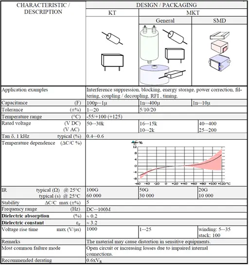
Sometimes polyester capacitors are called Mylar. The abbreviation PET above comes from Poly-Ethylene Terephtalate (also abbreviated PETP). On the pattern of European standards the common abbreviations is KT for film/foil design and MKT for metallized film. As ´polyester´ also Poly- Ethylene Naphtalate is using commercial abbreviation PEN.
Polyester PET Capacitors
The polyester film is most reliable and together with PP most used of the plastic films. It can be produced in thicknesses down to 0.7 μm (0.03 mils). Its tensional stability is high and its εr ≈ 3.2. This has facilitated manufacture of one for organic dielectrics very space-saving capacitor. A typical field of application is decoupling. Certain applications like switched mode power supplies (SMPS) require for filtering and decoupling purposes large capacitance and moderate losses which have made the MKT capacitor an attractive replacement for ceramic X7R capacitors. A common design may look like the one in Figure 17.
Furthermore the MKT capacitor can stand +125 °C. This has tempted a number of manufacturers to produce it in a chip design. But heat conditioned shrinking is most pronounced in PET capacitors. This has led to many setbacks just for the SM types. Today mainly two different methods apply for preventing such heat rises during the soldering procedures that they release a detrimental shrinking.
- The components are supplied with such encapsulations and electrode designs that the heat penetration into the component is obstructed.
- The molecular memory of the initial location before the elongation is deleted in a heat and pressure process during manufacture.
Thus the risk of shrinking is reduced with the latter method which is restricted to stacked designs only. Therefore the dimensions could be held down with a minimum of encapsulation. Then, however, the heat penetration will be higher and at temperatures of 230 °C the film material is damaged. One solves in other words the shrinking problem but increases risk of serious material damage. Soldering methods and temperatures have to be chosen and supervised so that the chosen capacitor type can stand these processes. An infrared (IR) reflecting film and IR soldering seem for the moment to be the only way out as long as we deal with traditional PET films. The latest films are more resistive specified for 125 °C and can endure peak temperatures reaching 235 °C at reflow soldering. The film manufacturer has altered the thermo-mechanical properties to reduce shrinkage when used as a dielectric in SMD capacitors.
The shrinking effects are best controlled by ESR measurements at the resonance frequency before and after soldering.
Advantages with PET
- Thin film with a high quality.
Disadvantages with PET
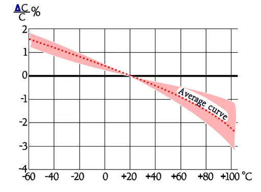
- The temperature dependence is comparatively large and non-linear.
- The dissipation factor is comparatively large, approximately 0.5% at 1 kHz.
- The material suffer from properties that in, for example, hi-fi applications (analogue technique) may give perceptible distortion.
Poly-Ethylene Naphtalate (PEN)
is a relative to polyester but somewhat more heat resistant. Capacitors with this dielectric often are presented under the title polyester. The material attracts the interest mostly for SMD designs. They are manufactured in stack technology with a film thickness of down to 1.5 μm (0.06 mils). According to some papers such chips are able to stand up to both wave and IR soldering but only IR and vapor phase soldering is recommended. However, recent developments and film improvements indicate a considerable step upwards in the temperature range. With a derating of the applied operating voltage above 125 °C an upper temperature of + 150°C is quite possible.
The material is still too expensive to be used on a large scale.
- Capacitance 1 nF… 10 μF.
- Tolerance ±5% and ±10%.
- Temperature range -55/+125°C (+150 °C).
- Rated voltage 16…400 V DC.
- Tanδ , 1kHz, 20°C, ≈ 0.4…0.5% (≤0,8%).
- IR, 20°C, ”typical” 30 000 s; ≥1 GΩ or ≥ 400 s.
- Stability ΔC/C ≤5%.
- TC ≈ +220±10ppm/°C (average over the temperature range).
- εr ≈ 3.2.
- Dielectric absorption ≈ 0.15 %.
- Recommended derating 0.6xVR.
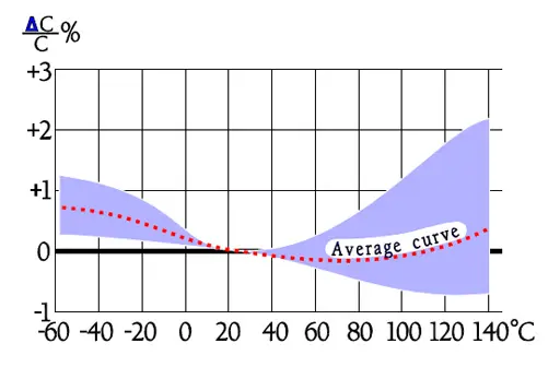
Temperature and frequency dependencies
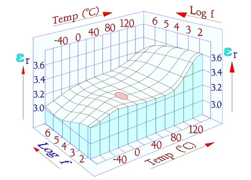
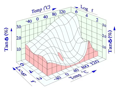
We will start with two three-dimensional diagrams that show how εr (and with that C) and Tanδ (DF) change with frequency and temperature. Specified measurement points have been inserted as ovals in the diagrams (Figure 18. and 19.).
The diagrams are interesting because they show how temperature and frequency rule the parameters in a complicated manner, especially Tanδ .
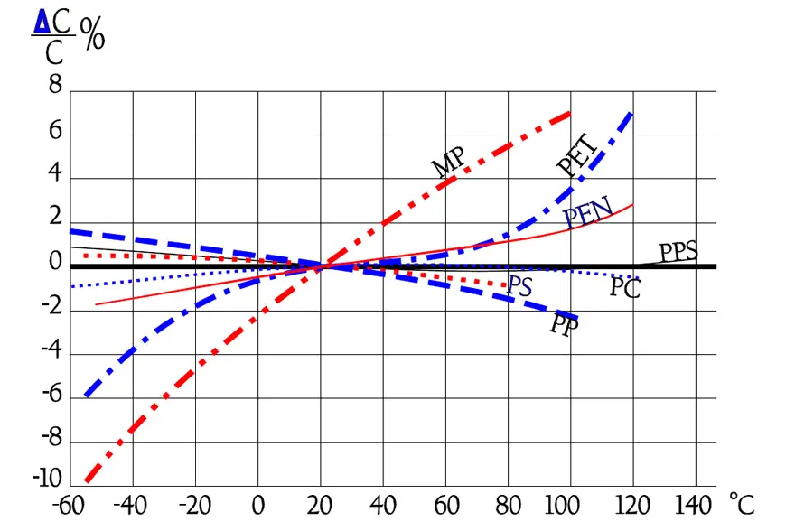
The following diagrams are more common and easy to interpret. In some of them there are curves inserted for a PEN, i.e., Poly Ethylene Naphtalate. It is comparatively more temperature resistant than PET and for that reason used in SMD types.
Among the curves over the frequency dependencies of impedance there are shown typical resonance frequency ranges. Because there are comparatively small changes of capacitance and the losses are rather small impedance diagrams get a pliable bend downwards into a sharp tip around the resonance frequency. Examples of resonance frequencies are shown in Figure 25.
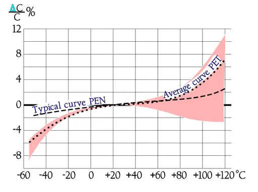
The temperature dependence of capacitance is influenced also by its magnitude, by the dielectric thickness and the design of the winding. This is reflected in the distribution at higher temperatures.
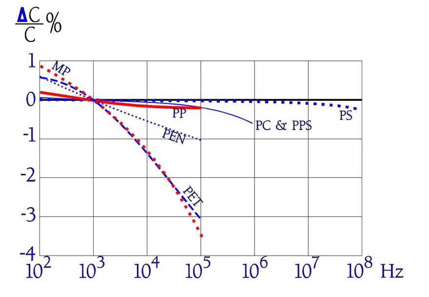
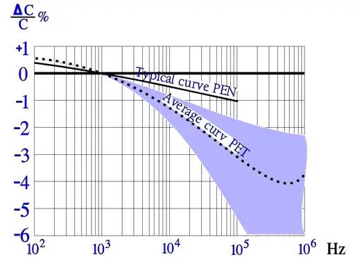
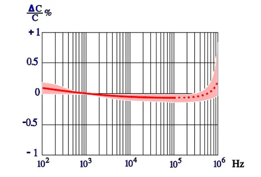
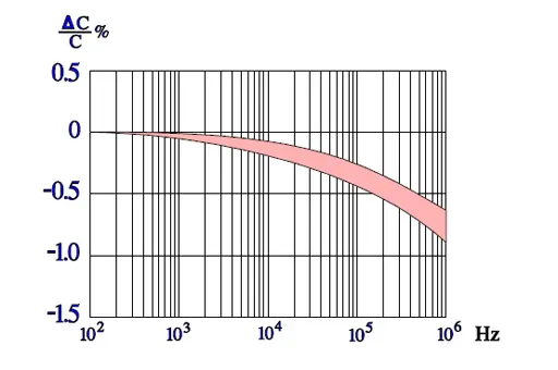
The frequency dependence of capacitance is ruled not only by the material but, to some extent, also by its magnitude and capacitor construction (foil or metallized design). Sometimes there are shown examples of series capacitance measurements where an apparent increase occurs at higher frequencies. This increase is hinted by the dotted line in Figure 21.
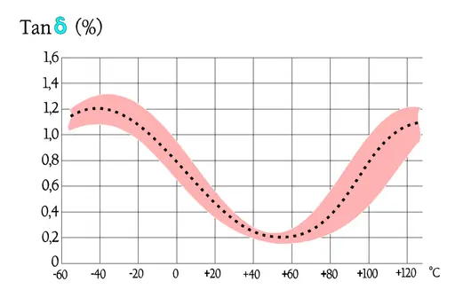
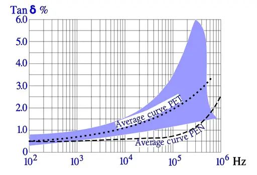
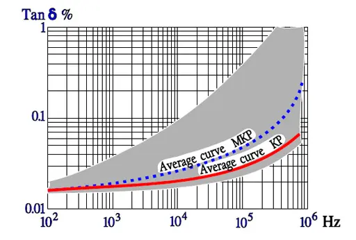
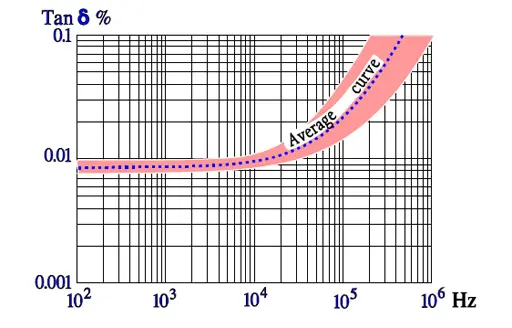
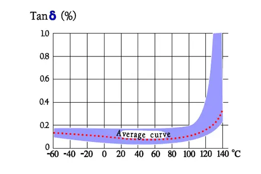
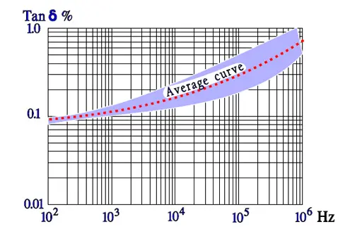
Also the frequency dependence of losses is ruled by the capacitance magnitude and by the design. While the dotted curve may represent a metallized design (MKT) in the magnitude of some hundred nF the foil capacitor (KT) is localized in the lower part of the curve area.
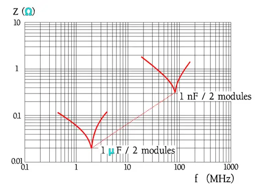
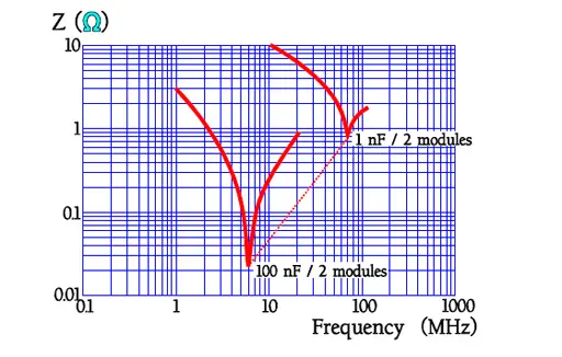
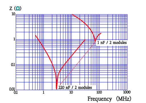
Other manufactures and other module distances give other resonance frequencies. Always check with the manufacturers’ data sheet.
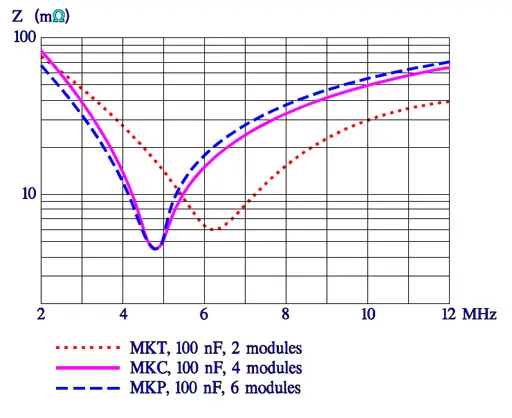
The seemingly sharp points in the impedance curve look in another magnification somewhat more round. Figure 26. shows results from measurements of MKT, MKC and MKP capacitors, 100nF. The slightly lower losses for MKC and MKP capacitors is shown as a lower ESR.
Failure modes
Bump, vibration and temperature cycling may in, above all hermetic cans, cause interruption in internal termination leads or in the connecting link terminal lead – spray metal compound – metallizing. Types that are molded into epoxy run less risk. If the casing on the other hand consists of plastic humidity will diffuse into the component. Humidity, however, impairs primarily only in the state of liquid (for example at a condensation) which will cause electrolysis, especially in the presence of a DC load. Thus non-hermetic components of this type or SMD design can bear a high RH, at least for 1000 hrs. If we can accept a C of +3 to +5% (εr for water approximately 80) and a decreasing IR there is no harm done. When the moisture content outside of the component decreases the humidity diffuses out of the winding and the capacitance increase goes back. If the component on the other hand operates in a jungle climate for months the IR will decrease until the leakage current starts electrolysis in the metallization. It will end in an open circuit.
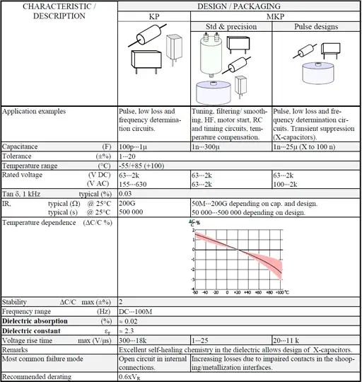
Polypropylene PP / KP and MKP Capacitors
The common European abbreviations for polypropylene capacitors is PP or KP for film/foil and MKP for metallized film.
Introduction
Polypropylene (PP) is from a molecular point of view a non-polar dielectric with small losses and a relatively straight and moderate TC. Since the smallest film thickness is approx. 3.5 μm (0.14 mils) and εr ≈ 2.3 the capacitor can not come down to those sizes characterizing PET at low rated voltages. But remaining good characteristics in many applications have brought up PP as a replacement for polycarbonate (PC) and polystyrene (PS), not least as a precision capacitor. PP exists in both foil and metallized design and is adopted for both AC, pulse and transient suppression (X-capacitor) applications. The pulse and X-capacitor designs, however, require a specific metallizing technology.
The MKP design had from the beginning problems with the adhesion between the metallized layer and the plastic film. This problem characterizes non-polar dielectrics consisting of molecules and has caused many problems at, for example, gluing of components to circuit boards. The plastic surface film has to be raised and roughened which among other things can be done by etching, flame exposure, electron irradiation or corona. Today the MKP design is well established and the adhesion problems a passed period.
The demand for filtering / interference suppression of thyristor generated noise voltages has brought forth the same type of large capacitors as shown for PET but here the low ESR losses allow quite different r.m.s. currents, for example at high frequencies.
The recommended absolute maximum temperature is +105°C. We recommend max +85°C with the remark that developments of new films is going on to offer temperature range above +105°C as a maximum operating temperature. Current temperature limitations still make PP difficult for chip designs.
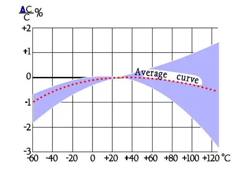
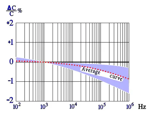
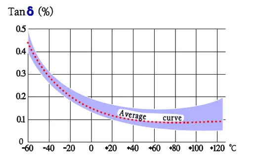
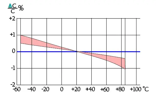
Temperature and frequency dependencies
The frequency dependence of capacitance for PP capacitors is moderate. In Figure 29. the broken part of the curve indicates an increase of capacitance. This increase is not physical but depends on influence from series capacitance measurements.
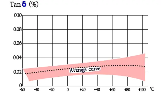
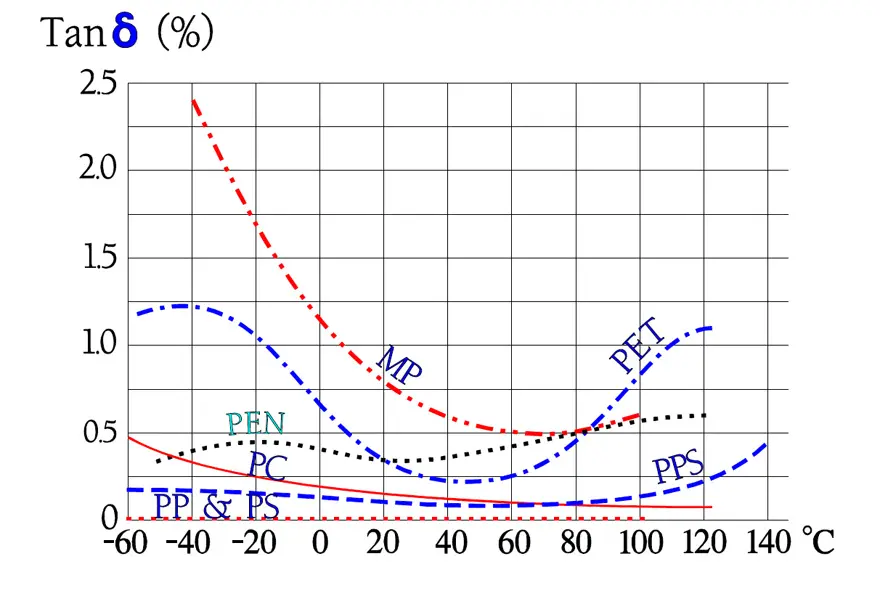
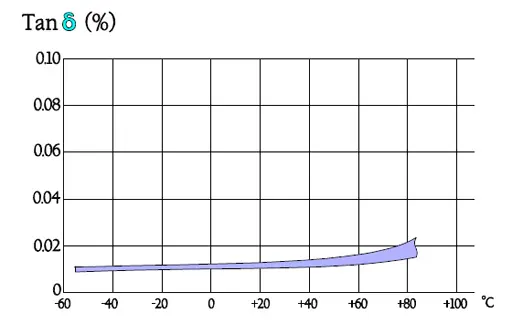
Note in Figure 30. the outstanding low loss factor for PP over the whole temperature range. The curve area in Figure 31. represents capacitance up to some hundreds of nF. The higher capacitance, the greater losses.
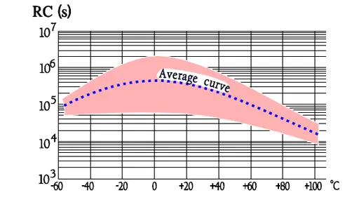
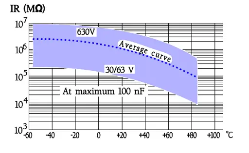
Designs with foil or hermetic seal have somewhat higher IR than corresponding metallized and plastic encapsulated types.
Thermal Model
Video with in-depth explanation of thermal polypropylene film capacitors can be find here: Thermal Model of PP Film Capacitors (passive-components.eu)
Failure modes
Any characteristic failure mode just for PP capacitors is not distinguishable. Here what was said about PET usually applies.
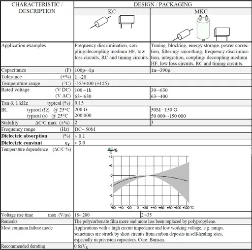
Polycarbonate (PC) capacitors / KC and MKC
For a long time the polycarbonate capacitor has been predominant among metallized precision capacitors. Nowadays, however, the PP capacitor has taken over more and more applications from the PC. Where one has been able to disregard the TC differences the foil design of the PC often has replaced polystyrene PS but also here PP capacitors are replacing those of polystyrene. The manufacture of PC film therefore is declining and, will eventually cease. We shall have a closer look on reasons and characteristics.
Introduction
The polycarbonate film is unlike other plastic films prepared from an emulsion that is dried. Its least thickness is stated to 1.5 μm (0.06 mils) and its εr to 3.0 at 1 kHz and room temperature. This film has small dielectric losses, a high IR, a small temperature dependence and a maximum temperature that by many manufacturers was specified to +125 °C. Thus it was rapidly popular, not least in precision capacitors.
Because there is a certain risk of increasing IR failures above +100 °C we recommend this ambient as a maximum or, not more than that of the manufacturer’s data sheet if they specify a lower temperature.
Genuine SMD designs are missing but there are examples of broad spread-out metal strap terminals reminding of the Gull wing design. But check if it is a single source situation.
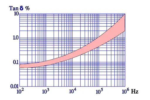
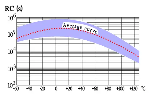
Temperature and frequency dependencies
Failure modes
Some mysterious short circuiting failures were reported from precision capacitors in high impedance low voltage space applications. In 1982 a Voyager satellite was met with a failure in a 8 μF/ 75V polycarbonate capacitor. Half-way to Jupiter the IR suddenly dropped from hundreds of MΩ to 2.8 kΩ. All over the world component experts worked with this kind of problem and by and by the picture became clearer. The reasons are resulting effects of a self-healing.
The issue is a critically high carbon deposit in former self-healing sites, which is connected with the high carbon contents in the polycarbonate film. But the failure only appears in that very narrow application sector where just precision capacitors usually are used, namely at low voltages and in high impedance circuits, e.g. integration and ramp voltages. Even that very low energy needed to burn away the formed carbon string may be missing. The cure is some kind of Burn-in treatment. From a failure rate in the magnitude of, say one per cent, we should get down to or below one per thousand. The most sophisticated (and expensive) Burn-in program we find in US MIL-C-87217. In conclusion it is built on a collection of all those environments which are regarded to release this kind of short circuits: cyclic voltage ramps with polarity changes + gradual temperature fluctuations.
Polystyrene (PS), Polyphenylene Sulfide (PPS), Teflon (PTFE) and Polysulfone (PSU) Film Capacitors
Polystyrene (PS) represents a non-polar dielectric material that just as polycarbonate to a great extent has been replaced by polypropylene. The availability is strongly limited due to ceased production.
Polyphenylene Sulfide or simply PPS has come to stay mainly because of its relatively high temperature resistance which has allowed SMD manufacture.
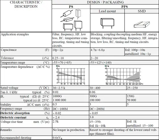
General Comments to PS
εr ≈ 2.4. Max. temp.+70°C (possibly +85°C). Smallest film thickness 4 μm (0.16 mils). Except for metal foils often double metallized plastic foils are used.
Advantages
- Very low losses; 0.01% at room ambient and 1 kHz.
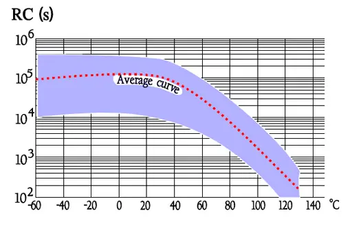
- Very high IR; RC 200 000 s. Actually it’s more exterior factors that determines the IR than the material itself.
- Dielectric absorption 0.02%.
- Stability ΔC/C, max ± 0.5%.
Disadvantages
- Can not be metallized due to high carbon deposits and too little oxygen available at a self-healing breakdown.
- Chemically sensitive film.
- Availability limited due to ceased production.
Temperature and frequency dependencies for PS
General comments to PPS
Foil types exist but metallized design is a rule. If nothing else is said metallized film applies.
εr ≈3.0. Max. temp.+140 °C; most manufacturers recommend maximum +125 °C. Dielectric absorption ≈ 0.1%.
Smallest film thickness is 1.2 μm (0.05 mils) but former quality problems with the thinnest film may give cause for stronger derating of the lowest rated voltage. However, the supply of film is stabilized thus indicating an established demand..
The film is used in capacitors both for lead mount and SMD. Existing chip types are made in a stacked design.
Temperature and frequency dependencies for PPS
Other plastic organic film capacitors used in special designs:
Teflon (PTFE)
Teflon exists both in metallized and foil design. The greatest advantage of the film is its temperature resistance. The price, on the other hand, is high which gives cause for exclusive hermetic designs.
- Capacitance 470pF….4.3μF.
- Tolerance ±0.25….±20%.
- Temperature range -65/+200°C.
- TC -200…+50ppm/°C.
- Rated voltage 50…600 V DC.
- Tanδ , @ 1kHz, 20°C, ≤0.1%.
- IR, @ 20°C, foil ≥500GΩ/ ≥100 000s,
- IR, @ 20°C, metallized film 50GΩ/ 10 000s.
- Stability ΔC/C max -1%.
- εr ≈ 2.2.
- Dielectric absorption ≤0.02%.
- Recommended derating 0.6xVR.
Polysulfone (PSU)
Polysulfone capacitors belong to the same price group as the one of teflon. They are used only in special applications where high temperature capabilities together with excellent characteristics are of vital importance. The capacitors have been manufactured only in hermetic design and with foil electrodes.
- Capacitance 1nF….22μF.
- Tolerance ±0.25….±10%.
- Temperature range -65/+150°C.
- TC -200…+50ppm/°C.
- Rated voltage 50…400 V DC.
- Tanδ , @ 1kHz, 20°C, ≤0.15%.
- IR, @ 20°C, foil ≥1000GΩ
- εr ≈ 3.2.
- Dielectric absorption ≤0.2%.
- Recommended derating 0.6xVR.