Passive Components Blog
No Result
View All Result
  • Home
  • NewsFilter
    • All
    • Aerospace & Defence
    • Antenna
    • Applications
    • Automotive
    • Capacitors
    • Circuit Protection Devices
    • electro-mechanical news
    • Filters
    • Fuses
    • Inductors
    • Industrial
    • Integrated Passives
    • inter-connect news
    • Market & Supply Chain
    • Market Insights
    • Medical
    • Modelling and Simulation
    • New Materials & Supply
    • New Technologies
    • Non-linear Passives
    • Oscillators
    • Passive Sensors News
    • Resistors
    • RF & Microwave
    • Telecommunication
    • Weekly Digest

    TDK Extends SMT Gate Drive Transformers to 1000 V

    Non-Linear MLCC Class II Capacitor Measurements Challenges

    Researchers Demonstrated HfO Anti-Ferroelectric Flexible Capacitors

    Connector Industry Achieves Double-Digit Growth

    Stackpole Unveils Metal Element High Current Chip Jumpers

    Common Mistakes in Flyback Transformer Specs

    Vishay Releases Miniature SMD Trimmers for Harsh Environments

    Würth Elektronik Releases Push-Button and Main Switches

    Littelfuse Unveils High-Precision TMR Angle Magnetic Sensors

    Trending Tags

    • Ripple Current
    • RF
    • Leakage Current
    • Tantalum vs Ceramic
    • Snubber
    • Low ESR
    • Feedthrough
    • Derating
    • Dielectric Constant
    • New Products
    • Market Reports
  • VideoFilter
    • All
    • Antenna videos
    • Capacitor videos
    • Circuit Protection Video
    • Filter videos
    • Fuse videos
    • Inductor videos
    • Inter-Connect Video
    • Non-linear passives videos
    • Oscillator videos
    • Passive sensors videos
    • Resistor videos

    Non-Linear MLCC Class II Capacitor Measurements Challenges

    Percolation Phenomenon and Reliability of Molded Power Inductors in DC/DC converters

    Root Causes and Effects of DC Bias and AC in Ceramic Capacitors

    How to Calculate the Output Capacitor for a Switching Power Supply

    Switched Capacitor Converter Explained

    Understanding Inductor Dot Markings and Their Application in LTspice

    Accelerating Full Bridge LLC Resonant Converter Design with Frenetic AI

    Understanding Switched Capacitor Converters

    Coupled Inductors Circuit Model and Examples of its Applications

    Trending Tags

    • Capacitors explained
    • Inductors explained
    • Resistors explained
    • Filters explained
    • Application Video Guidelines
    • EMC
    • New Products
    • Ripple Current
    • Simulation
    • Tantalum vs Ceramic
  • Knowledge Blog
  • Suppliers
    • Who is Who
  • Events
No Result
View All Result
Passive Components Blog
No Result
View All Result

Filters in Radar Receivers

28.3.2024
Reading Time: 4 mins read
A A

This article based on Knowles Precision Devices blog explains role and function of filter in radar receivers application.

In the article RF Components for Radar Application,  we provided an overview of the key functional units in radar, including duplexing, filtering, power amplification, waveform generation, low-noise amplification (LNA), receiving, and analog-to-digital conversion (ADC). While in the third installment we talked about filtering in terms of switch filter banks, in this post we will dive more into the jobs filters must perform in radar receivers.  

RelatedPosts

Knowles Unveils High-Performance Safety-Certified MLCC Capacitors

Knowles Releases Inductors for Mission-Critical RF Applications

Learn How Supercapacitors Enhance Power System in Knowles eBook

In general, filters are responsible for solving a variety of problems in the radar receiver. You can think of a filter as the problem-solving assistant in the system that comes along and tidies up different messes that are either outside the radar or made by components in the radar itself. Take a look at the radar functions diagram we discussed in the beginning of the series (Figure 1) and think about the receiver.  

Figure 1. Functional components of a radar system. 

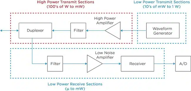
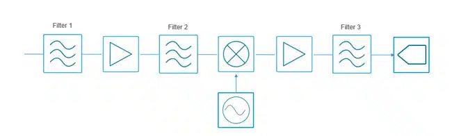
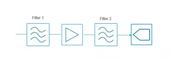
A typical heterodyne receiver has several filter jobs that need to be done, depending on the problems that need to be solved/messes that need to be cleaned up (Figure 2). Let’s take a closer look at these problems and the filtering technology that can be used to solve them. 

Figure 2. A diagram of a heterodyne receiver. 

Solving Signal Problems in a Radar Receiver with Filtering 

In the radar receiver, the first problem that must be solved is selecting the band of interest and removing any signals outside the band of interest that would confuse or overwhelm the receiver – this is what the first filter must take care of. The second problem to be solved is to remove any signals close enough to the band of interest that exist at mixer image. The second filter takes care of these mixer related messes.  

The third set of problems then arise when we get to the ADC. Here we need to remove any messes made by the amplifier and ensure the ADC only “sees” the correct alias band. A high-rejection filter close to the ADC can take care of this. In the case of the heterodyne approach, this job can be made easier by making the intermediate frequency (IF) fall well below the ADC’s Nyquist limit (which defines the maximum frequency that can be accurately captured and represented without distortion when using a specific sampling rate). 

With recent ADC technology innovations, it is now possible to perform direct sampling up to X band frequencies, depending on the sensitivity required. Since direct sampling digitizes signals directly, the mixer and some of the amplifiers in the receiver can be removed (Figure 3), eliminating some of the messes the filters need to clean up. 

Figure 3. An example of a direct sampling receiver.  

What we are left with when a direct sampling receiver is used is problem 1 – selecting the correct band of interest and removing out of band interference – and problem 3 – cleaning up the interference generated by the amplifier and selecting the alias bands of the ADC. We’ve effectively eliminated problem 2. Depending on the performance required in the receiver, and the RF input to the ADC, a high rejection level may be required to achieve this. For example, in an X band direct sampling system, you may see a broadband, low-loss, and high-rejection filter such as our B096QC2S in this role. 

As direct sampling receivers evolve, fully digital beamforming becomes realistic at some of the key radar bands such as S and X and eventually Ka. Knowles’ filter technology is rapidly advancing to keep pace with these possibilities. 

Related

Source: Knowles Precision Devices

Recent Posts

Radiation Tolerance of Tantalum and Ceramic Capacitors

8.8.2025
72

PCNS 2025 Final Program Announced!

4.8.2025
92

KYOCERA AVX Releases 600MHz Band71 Compact SAW Duplexer

30.7.2025
9

Researchers Demonstrated 200C Polymer Film Dielectric

28.7.2025
19

iNRCORE Releases New Range of 1KW HiRel Planar Transformers

24.7.2025
39

July 2025 Interconnect, Passives and Electromechanical Components Market Insights

23.7.2025
123

Exxelia Offers High-Q RF Microwave Capacitors for High Reliability Applications

21.7.2025
45

Knowles Releases Inductors for Mission-Critical RF Applications

15.7.2025
36

Murata Releases First High-Frequency XBAR Filter for Next-Gen Networks

8.7.2025
31

TDK Introduces High Current 80VDC Board-Mount EMI Filters

2.7.2025
42

Upcoming Events

Aug 27
17:00 - 18:00 CEST

Capacitor Assemblies for High-Power Circuit Designs

Sep 3
15:30 - 17:30 CEST

How to Choose Your Magnetic Supplier

Sep 16
17:00 - 18:00 CEST

EMI Shielding Challenges

Sep 22
September 22 @ 13:00 - September 25 @ 15:15 EDT

Pre Cap Visual Inspection per Mil-Std-883 (TM 2017)

Sep 30
September 30 @ 12:00 - October 2 @ 14:00 EDT

MIL-Std-883 TM 2010

View Calendar

Popular Posts

  • Buck Converter Design and Calculation

    0 shares
    Share 0 Tweet 0
  • Boost Converter Design and Calculation

    0 shares
    Share 0 Tweet 0
  • Flyback Converter Design and Calculation

    0 shares
    Share 0 Tweet 0
  • LLC Resonant Converter Design and Calculation

    0 shares
    Share 0 Tweet 0
  • What is a Dielectric Constant and DF of Plastic Materials?

    4 shares
    Share 4 Tweet 0
  • Ripple Current and its Effects on the Performance of Capacitors

    3 shares
    Share 3 Tweet 0
  • Dual Active Bridge (DAB) Topology Explained

    0 shares
    Share 0 Tweet 0
  • How to Design an Inductor

    0 shares
    Share 0 Tweet 0
  • MLCC Case Sizes Standards Explained

    0 shares
    Share 0 Tweet 0
  • Core Materials, Permeability and Their Losses

    0 shares
    Share 0 Tweet 0

Newsletter Subscription


Passive Components Blog

© EPCI - Leading Passive Components Educational and Information Site

  • Home
  • Privacy Policy
  • EPCI Membership & Advertisement
  • About

No Result
View All Result
  • Home
  • Knowledge Blog
  • Premium Suppliers

© EPCI - Leading Passive Components Educational and Information Site

This website uses cookies. By continuing to use this website you are giving consent to cookies being used. Visit our Privacy and Cookie Policy.
Go to mobile version