Passive Components Blog
No Result
View All Result
  • Home
  • NewsFilter
    • All
    • Aerospace & Defence
    • Antenna
    • Applications
    • Automotive
    • Capacitors
    • Circuit Protection Devices
    • electro-mechanical news
    • Filters
    • Fuses
    • Inductors
    • Industrial
    • Integrated Passives
    • inter-connect news
    • Market & Supply Chain
    • Market Insights
    • Medical
    • Modelling and Simulation
    • New Materials & Supply
    • New Technologies
    • Non-linear Passives
    • Oscillators
    • Passive Sensors News
    • Resistors
    • RF & Microwave
    • Telecommunication
    • Weekly Digest

    Modelithics Release Discrete Components Optimization Article for RF/Microwave Designers

    Samsung Extends Capacitance of MLCC 0805 X7T 250V to 100nF

    Samtec Releases 800-Position High-Performance Array Connectors  

    DigiKey Announces Back to School Giveaway to Empower Tomorrow’s Innovators

    Ripple Steering in Coupled Inductors: SEPIC Case

    TDK Releases Low Loss Thin-Film Inductors for AI Data Centers

    Samsung Releases Ultra–High-Capacitance 4.7uF 2.5V MLCC in 0201 for AI GPU

    SEPIC Converter with Coupled and Uncoupled Inductors

    Coupled Inductors in SEPIC versus Flyback Converters

    Trending Tags

    • Ripple Current
    • RF
    • Leakage Current
    • Tantalum vs Ceramic
    • Snubber
    • Low ESR
    • Feedthrough
    • Derating
    • Dielectric Constant
    • New Products
    • Market Reports
  • VideoFilter
    • All
    • Antenna videos
    • Capacitor videos
    • Circuit Protection Video
    • Filter videos
    • Fuse videos
    • Inductor videos
    • Inter-Connect Video
    • Non-linear passives videos
    • Oscillator videos
    • Passive sensors videos
    • Resistor videos

    Ripple Steering in Coupled Inductors: SEPIC Case

    SEPIC Converter with Coupled and Uncoupled Inductors

    Coupled Inductors in SEPIC versus Flyback Converters

    Non-Linear MLCC Class II Capacitor Measurements Challenges

    Percolation Phenomenon and Reliability of Molded Power Inductors in DC/DC converters

    Root Causes and Effects of DC Bias and AC in Ceramic Capacitors

    How to Calculate the Output Capacitor for a Switching Power Supply

    Switched Capacitor Converter Explained

    Understanding Inductor Dot Markings and Their Application in LTspice

    Trending Tags

    • Capacitors explained
    • Inductors explained
    • Resistors explained
    • Filters explained
    • Application Video Guidelines
    • EMC
    • New Products
    • Ripple Current
    • Simulation
    • Tantalum vs Ceramic
  • Knowledge Blog
  • Suppliers
    • Who is Who
  • Events
No Result
View All Result
Passive Components Blog
No Result
View All Result

Frenetic Presents its Online Leakage Inductance Model

9.7.2024
Reading Time: 3 mins read
A A

Frenetic published white paper with introduction of its online leakage inductance model and simulation of transformer leakage inductance behaviour.

Leakage inductance is crucial in many topologies such as flyback converters, dual active bridge converters, and resonant converters impacting operating parameters such as switching behaviour, overvoltage, and losses. Hence, it is imperative for the power electronic designer to estimate the value of transformer losses and leakage inductance in the design stage.

RelatedPosts

Common Mistakes in Flyback Transformer Specs

Accelerating Full Bridge LLC Resonant Converter Design with Frenetic AI

How to design a 60W Flyback Transformer

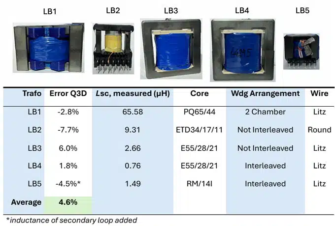
The accuracy of the Quasi-3D (Q3D) leakage inductance model is in the range of geometric uncertainties. The model is capable of calculating leakage inductance for arbitrarily positioned windings with benchmark accuracy of average error below 4.6% compared with measurements.

Model Features

  • Quasi-3D modelling concept
  • Analytical solutions
  • 2D-magnetic field
  • Windings can have arbitrary positions
  • Homogeneous current density assumed

How does it work?

Figure 1 – Quasi-3D modelling concept

Model Concept
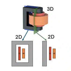
The Q3D model is based on splitting up the 3D transformer geometry into multiple winding sections with constant 2D cross sections as shown in Figure 1. Magnetic energy contributions of all winding sections are calculated and summed up to receive the overall magnetic energy. The total leakage inductance is then derived from the magnetic energy.

The magnetic energy contribution of each winding section is calculated using existing accurate analytical expressions. Specifically, the energy contribution of straight winding sections is calculated using Roth’s model. The energy of curved winding sections is based on the per unit angle calculation.

Benchmark Transformers & Results

The model has been verified by leakage impedance measurement with five carefully designed benchmark transformer prototypes of various types & winding configurations to maximize the significance of the verification.

The transformers are shown in Figure 2 below together with their properties and measured short circuit inductances along with their calculated leakage inductance.

Figure 2. transformer leakage inductance model vs measurement benchmark

Future Enhancements

Taking into account frequency efects such as skin-& proximity efect and circulating currents in parallel wires will be part of future extensions of the model.

The complete white paper is available for download from Frenetic upon form fill here

Related

Source: Frenetic

Recent Posts

Modelithics Release Discrete Components Optimization Article for RF/Microwave Designers

28.8.2025
3

Ripple Steering in Coupled Inductors: SEPIC Case

27.8.2025
5

TDK Releases Low Loss Thin-Film Inductors for AI Data Centers

27.8.2025
7

SEPIC Converter with Coupled and Uncoupled Inductors

26.8.2025
14

Coupled Inductors in SEPIC versus Flyback Converters

26.8.2025
11

TDK Extends SMT Gate Drive Transformers to 1000 V

20.8.2025
21

Non-Linear MLCC Class II Capacitor Measurements Challenges

19.8.2025
43

Researchers Demonstrated HfO Anti-Ferroelectric Flexible Capacitors

19.8.2025
19

Common Mistakes in Flyback Transformer Specs

15.8.2025
57

Littelfuse Unveils High-Precision TMR Angle Magnetic Sensors

13.8.2025
13

Upcoming Events

Sep 3
15:30 - 17:30 CEST

How to Choose Your Magnetic Supplier

Sep 16
17:00 - 18:00 CEST

EMI Shielding Challenges

Sep 22
September 22 @ 13:00 - September 25 @ 15:15 EDT

Pre Cap Visual Inspection per Mil-Std-883 (TM 2017)

Sep 30
September 30 @ 12:00 - October 2 @ 14:00 EDT

MIL-Std-883 TM 2010

Oct 17
12:00 - 14:00 EDT

External Visual Inspection per MIL-STD-883 TM 2009

View Calendar

Popular Posts

  • Buck Converter Design and Calculation

    0 shares
    Share 0 Tweet 0
  • Boost Converter Design and Calculation

    0 shares
    Share 0 Tweet 0
  • Flyback Converter Design and Calculation

    0 shares
    Share 0 Tweet 0
  • LLC Resonant Converter Design and Calculation

    0 shares
    Share 0 Tweet 0
  • What is a Dielectric Constant and DF of Plastic Materials?

    4 shares
    Share 4 Tweet 0
  • Ripple Current and its Effects on the Performance of Capacitors

    3 shares
    Share 3 Tweet 0
  • Dual Active Bridge (DAB) Topology Explained

    0 shares
    Share 0 Tweet 0
  • How to Design an Inductor

    0 shares
    Share 0 Tweet 0
  • Core Materials, Permeability and Their Losses

    0 shares
    Share 0 Tweet 0
  • MLCC Case Sizes Standards Explained

    0 shares
    Share 0 Tweet 0

Newsletter Subscription


Passive Components Blog

© EPCI - Leading Passive Components Educational and Information Site

  • Home
  • Privacy Policy
  • EPCI Membership & Advertisement
  • About

No Result
View All Result
  • Home
  • Knowledge Blog
  • Premium Suppliers

© EPCI - Leading Passive Components Educational and Information Site

This website uses cookies. By continuing to use this website you are giving consent to cookies being used. Visit our Privacy and Cookie Policy.
Go to mobile version