


This article, part of the Fuse Fundamentals series, has been prepared for the EPCI Knowledge Blog with cooperation and permission from Littelfuse. You can download the PDF version of the Fuse Fundamentals from Littelfuse’s website here. This comprehensive guide covers fuse characteristics and features in detail.
Introduction
All electrical systems eventually encounter overcurrents.
Unless promptly addressed, even moderate overcurrents can rapidly overheat system components, causing damage to insulation, conductors, and equipment. Significant overcurrents can melt conductors, burn insulation, and generate magnetic forces capable of bending and twisting bus bars. High currents can pull cables from their terminals and crack insulators and spacers.
The fires, explosions, and poisonous fumes resulting from uncontrolled overcurrents can result in injuries and fatalities. These hazards are easily preventable with adequate overcurrent protection. Electrical codes and other relevant design and installation standards establish requirements for overcurrent protection to mitigate these risks.
What Makes for High-Quality Overcurrent Protection?
A system with robust overcurrent protection should possess the following characteristics:
- It adheres to all applicable codes, including the NEC, CEC, and IEC.
- It prioritizes personnel safety by exceeding the minimum code regulations.
- It minimizes damage to property, equipment, and electrical systems caused by overcurrents.
- It provides coordinated protection (when the protective device immediately on the line side of an overcurrent opens to safeguard the system and minimize unnecessary downtime).
- It is cost-effective while offering ample interrupting capacity for future growth.
- It utilizes modern equipment and components that require minimal maintenance.
Overcurrent Types: Overloads vs. Short Circuits
Overloads
An overload refers to an overcurrent confined to normal current paths, where there is no insulation breakdown.
A common cause of sustained overloads is the installation of excessive equipment, such as additional lighting fixtures or an excessive number of motors. Sustained overloads can also be caused by overloaded mechanical equipment or equipment breakdowns, like failed bearings. If not interrupted within a specific timeframe, sustained overloads will eventually overheat circuit components and cause thermal damage to the insulation and other system components.
Overcurrent protection devices must interrupt circuits and equipment experiencing continuous or sustained overloads before overheating occurs. Even moderate insulation overheating can significantly reduce the lifespan of components, equipment, or both. For instance, motors overloaded by just 15% may experience less than 50% of their normal insulation life.
Temporary overloads are common occurrences. Common causes include a machine tool making an excessively deep cut or simply energizing an inductive load, such as a motor. Since most temporary overloads are harmless, it is generally advisable to not operate overcurrent protective devices during such situations.
It is crucial to understand that fuses must have sufficient time-out periods to prevent unnecessary interruptions and potential damage.
Delay for temporary overloads to subside. However, if the overcurrent persists, fuses must open before components are damaged. In general, time-delay fuses can withstand 500% of the rated current for a minimum of ten seconds. Nevertheless, they will quickly open during high-current faults.
Short Circuits
A short circuit occurs when an overcurrent flows outside its normal path. There are three main types of short circuits: bolted faults, arcing faults, and ground faults.
A short circuit can be caused by an insulation breakdown or an improper connection. During normal circuit operation, the connected load determines the current. However, when a short circuit happens, the current bypasses the normal load and takes a “shorter path,” hence the term “short circuit.” Since there’s no load impedance, the system impedance from the utility generator to the point of fault is the only factor that limits the current flow.
For instance, a typical electrical system might have a normal load impedance of 10 ohms. But in a short-circuit condition, this impedance becomes the only factor that restricts the current flow.
A typical electrical system might have a normal load impedance of 10 ohms. But in a short-circuit condition, this system may have a load impedance of 0.005 ohms or less.
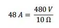
To compare these two scenarios, apply Ohm’s Law (current = voltage ÷ resistance). Thus, a 480-V single-phase circuit with a 10-ohm load impedance will draw 48 A:
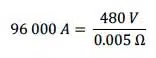
If the same circuit has a 0.005-ohm system impedance when the load is shorted, then the available short-circuit current will significantly increase to 96 000 A:
As mentioned earlier, short circuits are currents that flow outside their intended path. Regardless of the magnitude of the overcurrent, it’s crucial to interrupt the excessive current promptly. If not, the high current generated by a short circuit can have three severe consequences for an electrical system: heating, magnetic stress, and arcing.
Heating occurs whenever current flows through an electrical system. When overcurrents are extremely high, this heating becomes almost instantaneous. The energy dissipated in such overcurrents is measured in ampere-squared seconds (I2t). For instance, a 10,000-ampere overcurrent that lasts for 0.01 seconds has an I2t value of 1,000,000 A2s. Conversely, if we can reduce the current from 10,000 A to 1,000 A for the same duration, the corresponding I2t will decrease to 1,000,000 A2s, which is merely 1% of the original value.
If the current in a conductor increases by a factor of ten, the I2t will increase by a factor of 100. For instance, a current of just 7,500 A can cause a #8 AWG copper wire to melt in 0.1 seconds. Within 8 milliseconds (which is equivalent to one-half of an electrical cycle), a current of 6,500 A can raise the temperature of a #12 AWG THHN thermoplastic insulated copper wire from its operating temperature of 75 °C to its maximum short-circuit temperature of 150 °C.
Any currents exceeding these limits can instantly vaporize the conductor insulation. Arcs at the fault location or caused by mechanical switching (such as automatic transfer switches or circuit breakers) can ignite these vapors, leading to an arc flash. This explosion generates an intense burst of light and temperatures reaching up to 19,000 °C. The molten material can ignite nearby personnel and, when deposited on insulators and other surfaces, cause additional short circuits. The longer it takes for a protective device to activate, the larger the arc flash will be. This is precisely why it’s so essential to select the appropriate fuse for the specific application.
Magnetic stress, a function of the square of the peak current, can be high enough to damage insulation, pull conductors from terminals, and stress equipment terminals to the point of significant damage.
Whether the effects are heating, arcing, or magnetic stress, the potential damage to electrical systems can be catastrophic.
Read related article: Over voltage and over current protection explained
Fuse Characteristics and Features
Fuse characteristics and features play a crucial role in electrical protection. Time current characteristics determine how quickly a fuse responds to overcurrents. A quick response time is essential for the system’s protection. Fuse opening times are inversely proportional to the current magnitude. As the magnitude of overcurrent increases, the fuse opening time decreases.
When properly rated according to NEC requirements, fuses provide both overload and short-circuit protection to the system conductors and components. However, in certain instances, such as when fuses are used to backup circuit breakers or provide motor branch short-circuit protection and ground-fault protection, fuses may only offer short-circuit protection.
The most important factors to consider when selecting fuses include:
- Operating characteristic: This defines a fuse’s general performance, which can be time-delay, fast-acting, or very fast-acting (also known as high-speed).
- Effect of ambient temperature: Fuses must be designed to withstand varying temperatures to ensure reliable performance.
- Current limitation: The fuse must have a current rating that is sufficient to protect the system from overcurrents.
- Physical size: The fuse must be physically small enough to fit in the designated space.
- Indication: The fuse must have an indication to show when it has tripped.
- Current rating: The current rating specifies the maximum current that the fuse can handle.
- Voltage rating: The voltage rating specifies the maximum voltage that the fuse can withstand.
- Interrupting rating: The interrupting rating specifies the maximum interrupting current that the fuse can handle.
Operating Characteristic
A fuse’s operating characteristic defines a fuse’s general performance.This may be time delay, fast acting, or very fast acting (also known as high speed).
Effect of Ambient Temperature
Fuses are a thermal device that are impacted by ambient temperatures.Elevated ambient temperatures can effectively “derate” a fuse’s current carrying capacity to be much less than its marked rating.There are published derating curves that should be considered.
Current Limitation
Current-limiting fuses significantly reduce the total destructive heat energy (I2t) to the circuit and its components. They open and clear short circuits in less than 180 electrical degrees (the first half of the electrical cycle).
NEC Article 240—Overcurrent Protection states that a current-limiting overcurrent protective device must reduce the peak let-through current to a value substantially less than the potential peak current without protection or if the fuses were replaced with solid conductors of the same impedance.
Apart from supplemental and Class K fuses, almost all other fuse types used in modern electrical systems and applications are considered current limiting based on these parameters.
When selecting fuses for your system, determine the level of current limitation required by your overcurrent protective devices. Peak let-through curves, discussed in greater detail on page 10, will indicate the current limiting capabilities of a specific fuse.
Physical Size
While often overlooked, consider the overall dimensions of the fuse. Use the size and dimensions of either the fuse block or the disconnect switch where the fuse is installed.
While saving space may be a crucial factor in fuse selection, other considerations should not be disregarded. Some of these include:
- Whether the smallest fuse has the most suitable characteristics for the application.
- Whether the equipment where the fuse will be installed provides adequate space for maintenance.
Whether the smallest fuse harmonizes well with the system’s other overcurrent protection devices.
If considering only physical dimensions, a 600-volt, 60-ampere fuse would be an example.
A 200,000-ampere interrupting rating, time-delay, dual-element UL Class CD fuse is smaller than a similarly rated UL Class J fuse, which is, in turn, considerably smaller than a similarly rated UL Class RK1 or Class RK5 fuse. However, smaller-sized fuses may have less time delay and be faster-acting, which could cause more nuisance openings compared to their larger counterparts. Therefore, choosing the smallest fuse isn’t always the optimal solution.
Indication:
Fuse indication allows you to quickly identify which fuses have opened. Many common UL fuse classes are available in both indicating and non-indicating versions. Indication can reduce downtime by enabling a maintenance technician to swiftly determine if the fuse has operated or not.
The Littelfuse POWR-PRO® LLSRK_ID (Class RK1), JTD_ID (Class J), and FLNR_ID, FLSR_ID, and IDSR (Class RK5) fuse series have built-in indication.
Current Rating:
A fuse’s current rating specifies the continuous ac or dc current it can handle under specified conditions. Fuses selected for a circuit must meet NEC requirements, as outlined in NEC Articles 240 and 430. These NEC requirements establish maximum and, in some cases, minimum ratings. When selecting a fuse, it’s recommended to choose a current rating as close to the system’s typical operating current as possible.
Voltage Rating:
A fuse’s voltage rating indicates the maximum ac or dc voltage it can withstand. Fuse voltage ratings must be equal to or exceed the maximum circuit voltage where the fuses are installed. Fuses in dc circuits must be specifically rated for dc applications.
Fuses can be rated for ac only, dc only, or both ac and dc. However, exceeding the voltage ratings or using an ac-only fuse in a dc circuit can lead to severe fuse failure.
Exceeding the voltage ratings or using an ac-only fuse in a dc circuit may lead to serious fuse failure
Interrupting Rating
A fuse’s interrupting rating is the highest fault current it can safely interrupt at its rated voltage under standardized test conditions. All UL-listed fuses must safely interrupt all overcurrents between their current rating and interrupting rating. Standard UL fuses are available with interrupting ratings up to 300,000 A.
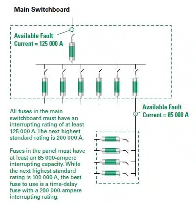
According to NEC Article 110.9, equipment designed to interrupt current at fault levels must have an interrupting rating at nominal circuit voltage that is at least equal to the available fault current at the line terminals of the equipment.
This is illustrated in Figure 1.
It is crucial to select fuses with interrupting ratings that are equal to or exceed the available short-circuit current (also known as available fault current and prospective fault current).
Standardizing fuses with an interrupting rating of at least 200,000 amperes ensures that all fuses have sufficient interrupting capacity. It also provides a reserve interrupting capacity for future increases in available short-circuit current.
Further read:


