Passive Components Blog
No Result
View All Result
  • Home
  • NewsFilter
    • All
    • Aerospace & Defence
    • Antenna
    • Applications
    • Automotive
    • Capacitors
    • Circuit Protection Devices
    • electro-mechanical news
    • Filters
    • Fuses
    • Inductors
    • Industrial
    • Integrated Passives
    • inter-connect news
    • Market & Supply Chain
    • Market Insights
    • Medical
    • Modelling and Simulation
    • New Materials & Supply
    • New Technologies
    • Non-linear Passives
    • Oscillators
    • Passive Sensors News
    • Resistors
    • RF & Microwave
    • Telecommunication
    • Weekly Digest

    Bourns Releases Automotive High Creepage and Clearance Transformer

    Bourns Unveils Metal Powder Core High Current Low DCR Shielded Power Inductor

    Influence of Tantalum Capacitor Pellets Size on Stability During Oxide Film Formation

    Modelithics Release Discrete Components Optimization Article for RF/Microwave Designers

    Samsung Extends Capacitance of MLCC 0805 X7T 250V to 100nF

    Samtec Releases 800-Position High-Performance Array Connectors  

    DigiKey Announces Back to School Giveaway to Empower Tomorrow’s Innovators

    Ripple Steering in Coupled Inductors: SEPIC Case

    TDK Releases Low Loss Thin-Film Inductors for AI Data Centers

    Trending Tags

    • Ripple Current
    • RF
    • Leakage Current
    • Tantalum vs Ceramic
    • Snubber
    • Low ESR
    • Feedthrough
    • Derating
    • Dielectric Constant
    • New Products
    • Market Reports
  • VideoFilter
    • All
    • Antenna videos
    • Capacitor videos
    • Circuit Protection Video
    • Filter videos
    • Fuse videos
    • Inductor videos
    • Inter-Connect Video
    • Non-linear passives videos
    • Oscillator videos
    • Passive sensors videos
    • Resistor videos

    Ripple Steering in Coupled Inductors: SEPIC Case

    SEPIC Converter with Coupled and Uncoupled Inductors

    Coupled Inductors in SEPIC versus Flyback Converters

    Non-Linear MLCC Class II Capacitor Measurements Challenges

    Percolation Phenomenon and Reliability of Molded Power Inductors in DC/DC converters

    Root Causes and Effects of DC Bias and AC in Ceramic Capacitors

    How to Calculate the Output Capacitor for a Switching Power Supply

    Switched Capacitor Converter Explained

    Understanding Inductor Dot Markings and Their Application in LTspice

    Trending Tags

    • Capacitors explained
    • Inductors explained
    • Resistors explained
    • Filters explained
    • Application Video Guidelines
    • EMC
    • New Products
    • Ripple Current
    • Simulation
    • Tantalum vs Ceramic
  • Knowledge Blog
  • Suppliers
    • Who is Who
  • Events
No Result
View All Result
Passive Components Blog
No Result
View All Result

Fuse Protection against thermal runaway

29.9.2017
Reading Time: 2 mins read
A A

source: Schurter application note

A thermal runaway is an increasing threat to electronic devices where more and more power is packed in ever smaller spaces; it is a threat that is poorly dealt with using traditional means. SMD thermal fuses offer a solution that can be reflow-soldered at 260°C and still open at 210°C.

RelatedPosts

Bourns Releases Automotive High Creepage and Clearance Transformer

Bourns Unveils Metal Powder Core High Current Low DCR Shielded Power Inductor

Influence of Tantalum Capacitor Pellets Size on Stability During Oxide Film Formation

What is meant by a thermal runaway or the thermal damage of power semiconductors: A thermal runaway refers to the overheating of a technical apparatus due to a self-reinforcing process that
generates heat. This damage usually causes the destruction of the apparatus and often leads to a fire or explosion.

Causes

The causes of a thermal runaway are varied and often random in nature. However, the ever-higher power density in electronic wiring and the trend towards miniaturization are without a doubt of
particular importance. More and more functions are packed in compact modules, which then also have a correspondingly high power consumption. Even slightly excessive currents in power electronics with only a little power loss lead to elevated temperatures of approximately 200°C.

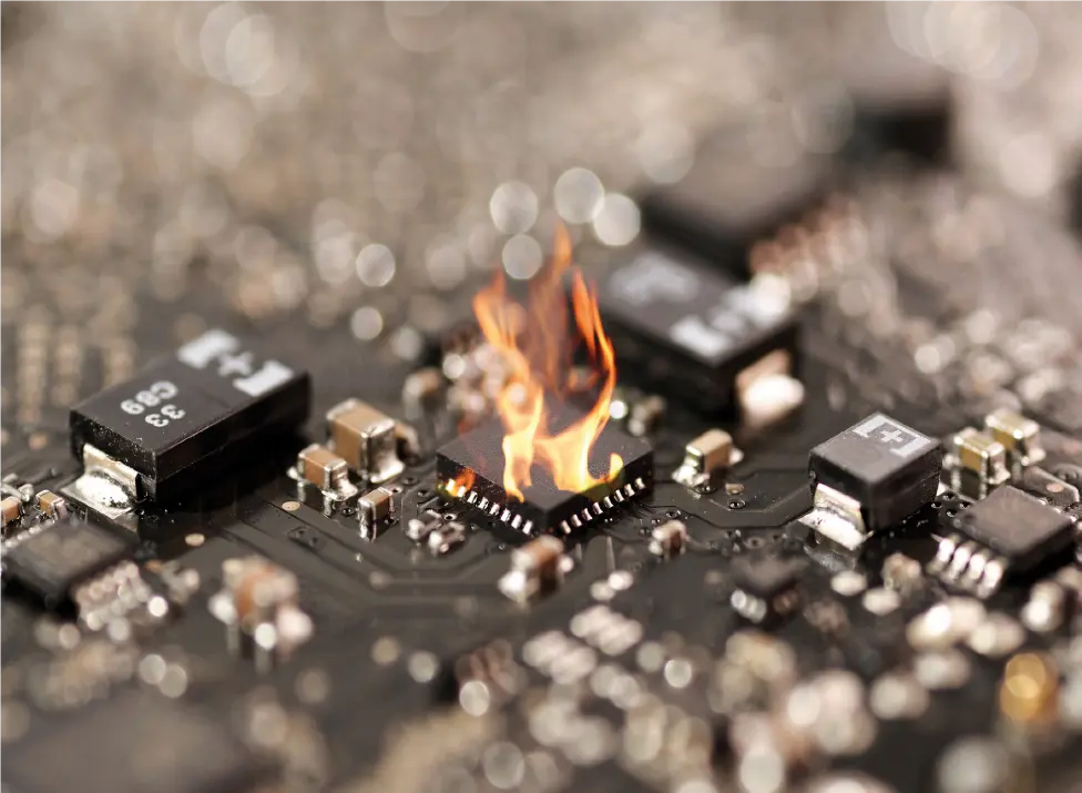
The possible consequences: damage or disconnection of surrounding components, damage to the printed circuit board structure or, in the worst case, the triggering of a fire.

Build up

With a power semiconductor (e.g. MOSFET) the drain-source transmission resistance increases with rising temperatures, when connected, which results in an increasing loss of power
in the barrier layer. If the elements are not sufficiently cooled – the high power density permits cooling – the power loss output in the form of heat can no longer be sufficiently dissipated, which also increases the transmission resistance. This process escalates and ultimately leads to destruction of the component.

How to protect against a short circuit?
The cooling of a system must dissipate at least as much energy as it is supplied with. The overcurrent during a thermal runaway is too low to cause a conventional fuse to trip. Thermal circuit breakers or PTCs would, in principle, be used, but the products available for the assembly of an SMD printed circuit board are too complicated or completely unsuitable.
Solution
SCHURTER develops and manufactures SMD thermal fuses with the lowest possible internal resistance for power electronics of the highest packing density. They can be reflow-soldered at a
maximum temperature of 260°C without opening. The temperature trigger is therefore around 210°C during operation.
This corresponds to a range above normal component temperature ratings, but still below the limit to create serious consequences. The fuse opens with or without current flow depending on the
temperature. Such irreversible thermal fuses are resistant to mechanical shock, vibration, thermal shock, temperature cycles and moisture. They are qualified according to AEC-Q200.

Related

Recent Posts

Bourns Releases Automotive High Creepage and Clearance Transformer

1.9.2025
6

Bourns Unveils Metal Powder Core High Current Low DCR Shielded Power Inductor

29.8.2025
16

Samsung Extends Capacitance of MLCC 0805 X7T 250V to 100nF

28.8.2025
20

DigiKey Announces Back to School Giveaway to Empower Tomorrow’s Innovators

27.8.2025
12

TDK Releases Low Loss Thin-Film Inductors for AI Data Centers

27.8.2025
16

Vishay Releases High Current 3.3 V to 36 V ESD Protection Diodes

25.8.2025
15

TDK Extends SMT Gate Drive Transformers to 1000 V

20.8.2025
22

Stackpole Unveils Metal Element High Current Chip Jumpers

19.8.2025
46

Vishay Releases Miniature SMD Trimmers for Harsh Environments

14.8.2025
22

Littelfuse Unveils High-Precision TMR Angle Magnetic Sensors

13.8.2025
19

Upcoming Events

Sep 3
15:30 - 17:30 CEST

How to Choose Your Magnetic Supplier

Sep 16
17:00 - 18:00 CEST

EMI Shielding Challenges

Sep 22
September 22 @ 13:00 - September 25 @ 15:15 EDT

Pre Cap Visual Inspection per Mil-Std-883 (TM 2017)

Sep 30
September 30 @ 12:00 - October 2 @ 14:00 EDT

MIL-Std-883 TM 2010

Oct 17
12:00 - 14:00 EDT

External Visual Inspection per MIL-STD-883 TM 2009

View Calendar

Popular Posts

  • Buck Converter Design and Calculation

    0 shares
    Share 0 Tweet 0
  • Boost Converter Design and Calculation

    0 shares
    Share 0 Tweet 0
  • Flyback Converter Design and Calculation

    0 shares
    Share 0 Tweet 0
  • LLC Resonant Converter Design and Calculation

    0 shares
    Share 0 Tweet 0
  • What is a Dielectric Constant and DF of Plastic Materials?

    4 shares
    Share 4 Tweet 0
  • Ripple Current and its Effects on the Performance of Capacitors

    3 shares
    Share 3 Tweet 0
  • Dual Active Bridge (DAB) Topology Explained

    0 shares
    Share 0 Tweet 0
  • How to Design an Inductor

    0 shares
    Share 0 Tweet 0
  • Core Materials, Permeability and Their Losses

    0 shares
    Share 0 Tweet 0
  • MLCC Case Sizes Standards Explained

    0 shares
    Share 0 Tweet 0

Newsletter Subscription


Passive Components Blog

© EPCI - Leading Passive Components Educational and Information Site

  • Home
  • Privacy Policy
  • EPCI Membership & Advertisement
  • About

No Result
View All Result
  • Home
  • Knowledge Blog
  • Premium Suppliers

© EPCI - Leading Passive Components Educational and Information Site

This website uses cookies. By continuing to use this website you are giving consent to cookies being used. Visit our Privacy and Cookie Policy.
Go to mobile version