Passive Components Blog
No Result
View All Result
  • Home
  • NewsFilter
    • All
    • Aerospace & Defence
    • Antenna
    • Applications
    • Automotive
    • Capacitors
    • Circuit Protection Devices
    • electro-mechanical news
    • Filters
    • Fuses
    • Inductors
    • Industrial
    • Integrated Passives
    • inter-connect news
    • Market & Supply Chain
    • Market Insights
    • Medical
    • Modelling and Simulation
    • New Materials & Supply
    • New Technologies
    • Non-linear Passives
    • Oscillators
    • Passive Sensors News
    • Resistors
    • RF & Microwave
    • Telecommunication
    • Weekly Digest

    TDK Releases 140C Compact Vibration Robust Automotive Aluminum Capacitors

    DigiKey Presents Factory Tomorrow Season 5 Video Series

    Samsung MLCCs Lineup for In-Vehicle Infotainment

    source: Samtec

    Best Practices for Cable Management in High-Speed and High-Density Systems

    Würth Elektronik Unveils Compact Common-Mode Data Lines Chokes

    Bourns Releases TCO 240 Watt USB Mini-Breaker

    Littelfuse Adds 600W Automotive TVS Diodes for High-Energy Transient Protection

    Vishay Releases Harsh Environment Robust DC-Link Film Capacitor

    Bourns Releases Automotive High Creepage and Clearance Transformer

    Trending Tags

    • Ripple Current
    • RF
    • Leakage Current
    • Tantalum vs Ceramic
    • Snubber
    • Low ESR
    • Feedthrough
    • Derating
    • Dielectric Constant
    • New Products
    • Market Reports
  • VideoFilter
    • All
    • Antenna videos
    • Capacitor videos
    • Circuit Protection Video
    • Filter videos
    • Fuse videos
    • Inductor videos
    • Inter-Connect Video
    • Non-linear passives videos
    • Oscillator videos
    • Passive sensors videos
    • Resistor videos

    Ripple Steering in Coupled Inductors: SEPIC Case

    SEPIC Converter with Coupled and Uncoupled Inductors

    Coupled Inductors in SEPIC versus Flyback Converters

    Non-Linear MLCC Class II Capacitor Measurements Challenges

    Percolation Phenomenon and Reliability of Molded Power Inductors in DC/DC converters

    Root Causes and Effects of DC Bias and AC in Ceramic Capacitors

    How to Calculate the Output Capacitor for a Switching Power Supply

    Switched Capacitor Converter Explained

    Understanding Inductor Dot Markings and Their Application in LTspice

    Trending Tags

    • Capacitors explained
    • Inductors explained
    • Resistors explained
    • Filters explained
    • Application Video Guidelines
    • EMC
    • New Products
    • Ripple Current
    • Simulation
    • Tantalum vs Ceramic
  • Knowledge Blog
  • Suppliers
    • Who is Who
  • Events
No Result
View All Result
Passive Components Blog
No Result
View All Result

High Voltage MLCC for EV Powertrain

21.7.2022
Reading Time: 5 mins read
A A

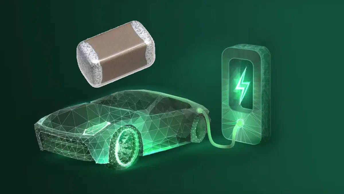
This article published by Samsung Electro-Mechanics discusses electric vehicle technology using high voltage applications and high voltage automotive MLCC ceramic capacitors.

The global car market is going through a massive transition to electric vehicles. So far, internal combustion engine (ICE) vehicles have improved powertrains to cope with emission regulations.

RelatedPosts

Samsung MLCCs Lineup for In-Vehicle Infotainment

Samsung Extends Capacitance of MLCC 0805 X7T 250V to 100nF

Samsung Releases Ultra–High-Capacitance 4.7uF 2.5V MLCC in 0201 for AI GPU

Emission regulations, convenience technologies and self-driving have driven electrification increases with automobiles.

As the number of electronic units increased, the amount of power consumption for a vehicle increased. Battery voltages have changed to deal with increased power consumption requirements, and they are associated with efficient power systems.

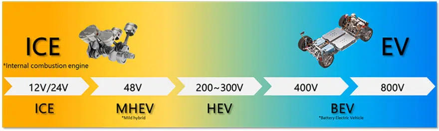
Vehicle Electrification and Battery Voltages

The battery voltage increase of the car is related to the trend of electrification. In order to understand the electrification trend, we must first look back on how the voltage of a car battery has changed. Before the mid-1950s, a vehicles operating voltage was 6V. Since then, the engine displacements increased and required a large electric starter motor.  The 12V system became standardized in the need of more electronic devices. Historically, early cars only needed a small battery to crank engine and turn on the radio.

However, as the number of in vehicle electronic devices has increased over time, so has the need for more power. To resolve this problem, discussions took place to increase the voltage from 12V to a higher voltage system capable of dealing with the additional power demand. In the 1990s, the 42V system was proposed, and in 2011, German carmakers made 48V the standard. Since then, hybrid cars and electric vehicles have begun to use higher voltages. Power (Watt) is voltage (V)*current (A). When increasing power, it is more efficient to raise the voltage rather than the current. When current is increased, thicker cables are required and connector pins must also be changed. Both have an impact on the hardware cost. So, battery voltages increased instead of current.

Battery voltage increase, 48V Mild Hybrid System

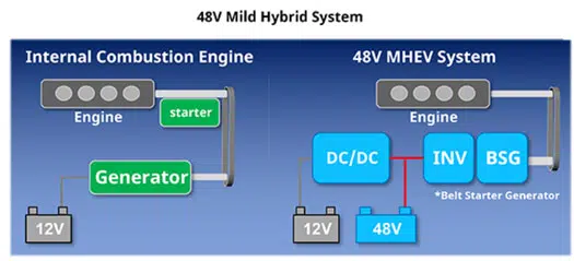
The main reason why the 48V system emerged in the 2010s was due to emission regulation.

Automakers producing internal combustion engines had to achieve their emission goals and increase fuel efficiency by improving powertrains. Mild Hybrid (MHEV) is said to be a simple inexpensive hybrid system. The reason why car manufacturers preferred MHEV is because it was easy to manufacture. The MHEV system can be manufactured by adding a 48V system to the existing internal combustion engine powertrain , emission reduction can be achieved at a lower cost than full-hybrid. But the question remains; why was 48V selected in particular? The reason is that,in many countries, 60V is regarded as a low voltage and not dangerous to the human body. In addition to the above, telephone lines have used 48V power systems for the last 100 years, which further proves the safety aspect of 48V systems in vehicles.

High voltage application in the electric car

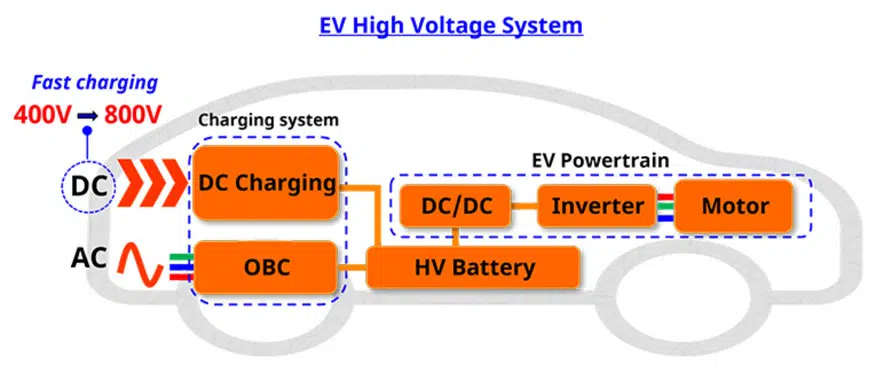
The basic powertrain configuration of electric vehicles consists of high voltage battery, inverter, and electric motor. EV powertrains use high voltage . The efficiency of an EV is linked to the efficiency of the DC/DC converter . Electric cars have various power conversion applications such as LDC, OBC, and Inverter. Various DC/DC Converter Topologies are being applied to integrate similar applications. For example, OBC (On Board Charger) and LDC (Low-Voltage DC/DC Converter) are under development for the system integration which have an advantage of reducing components and saving spaces.

High Voltage MLCC structure for guaranteed reliability

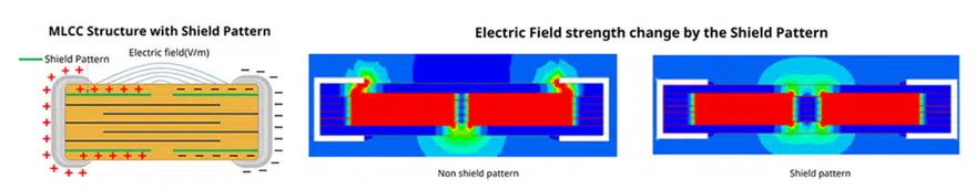
How is the structure of high voltage MLCC different from that of general MLCC? Reliability should be guaranteed in high voltage environments. MLCC applied  for high voltage applications are exposed to the risk of Arc-over and a short-circuit can occur inside of the MLCC. Under high voltage, a strong electric field is formed around the MLCC, which ionizes the surrounding air.  Particularly, a strong electric field is concentrated on both terminals of the MLCC. If it exceeds the inception voltage of the ionized air, electrical arcs occurs, ultimately leading to a short-circuit inside the MLCC. The structure that prevents this phenomenon is a shield pattern inside MLCC.

Floating design is a design that lowers the short-circuit risk when MLCC crack occurs, but it is also useful for high-voltage products. The floating structure distributes voltage so the voltage inside the MLCC is only half of the voltage applied to the end terminals. For example, when 1000V is applied to both ends of the MLCC, if the floating design is used only 500V is applied to the MLCC dielectric layer, which is half of 1000V. It’s definitely an advantage from the perspective of reliability because the electric field applied between dielectric layers decreases. Voltage along with temperature are key factors to determine MLCC lifetime. High Voltage MLCC guarantees reliability in high voltage applications.


Samsung EV application video:

Further reading:

  • High Voltage MLCC Dual-Use Legislation Considerations
  • High Voltage MLCCs Arc-Over Prevention

Related

Source: Samsung Electro-Mechanics

Recent Posts

TDK Releases 140C Compact Vibration Robust Automotive Aluminum Capacitors

5.9.2025
4

Samsung MLCCs Lineup for In-Vehicle Infotainment

4.9.2025
14

Littelfuse Adds 600W Automotive TVS Diodes for High-Energy Transient Protection

2.9.2025
9

Vishay Releases Harsh Environment Robust DC-Link Film Capacitor

2.9.2025
29

Bourns Releases Automotive High Creepage and Clearance Transformer

1.9.2025
25

Bourns Unveils Metal Powder Core High Current Low DCR Shielded Power Inductor

29.8.2025
27

Influence of Tantalum Capacitor Pellets Size on Stability During Oxide Film Formation

29.8.2025
34

Modelithics Release Discrete Components Optimization Article for RF/Microwave Designers

28.8.2025
13

Samsung Extends Capacitance of MLCC 0805 X7T 250V to 100nF

28.8.2025
32

Samsung Releases Ultra–High-Capacitance 4.7uF 2.5V MLCC in 0201 for AI GPU

27.8.2025
41

Upcoming Events

Sep 16
17:00 - 18:00 CEST

EMI Shielding Challenges

Sep 22
September 22 @ 13:00 - September 25 @ 15:15 EDT

Pre Cap Visual Inspection per Mil-Std-883 (TM 2017)

Sep 30
September 30 @ 12:00 - October 2 @ 14:00 EDT

MIL-Std-883 TM 2010

Oct 17
12:00 - 14:00 EDT

External Visual Inspection per MIL-STD-883 TM 2009

Oct 20
October 20 - October 23

Digital WE Days 2025 – Virtual Conference

View Calendar

Popular Posts

  • Buck Converter Design and Calculation

    0 shares
    Share 0 Tweet 0
  • Boost Converter Design and Calculation

    0 shares
    Share 0 Tweet 0
  • Flyback Converter Design and Calculation

    0 shares
    Share 0 Tweet 0
  • LLC Resonant Converter Design and Calculation

    0 shares
    Share 0 Tweet 0
  • What is a Dielectric Constant and DF of Plastic Materials?

    4 shares
    Share 4 Tweet 0
  • Ripple Current and its Effects on the Performance of Capacitors

    3 shares
    Share 3 Tweet 0
  • Dual Active Bridge (DAB) Topology Explained

    0 shares
    Share 0 Tweet 0
  • How to Design an Inductor

    0 shares
    Share 0 Tweet 0
  • Core Materials, Permeability and Their Losses

    0 shares
    Share 0 Tweet 0
  • MLCC and Ceramic Capacitors

    0 shares
    Share 0 Tweet 0

Newsletter Subscription


Passive Components Blog

© EPCI - Leading Passive Components Educational and Information Site

  • Home
  • Privacy Policy
  • EPCI Membership & Advertisement
  • About

No Result
View All Result
  • Home
  • Knowledge Blog
  • Premium Suppliers

© EPCI - Leading Passive Components Educational and Information Site

This website uses cookies. By continuing to use this website you are giving consent to cookies being used. Visit our Privacy and Cookie Policy.
Go to mobile version