Passive Components Blog
No Result
View All Result
  • Home
  • NewsFilter
    • All
    • Aerospace & Defence
    • Antenna
    • Applications
    • Automotive
    • Capacitors
    • Circuit Protection Devices
    • electro-mechanical news
    • Filters
    • Fuses
    • Inductors
    • Industrial
    • Integrated Passives
    • inter-connect news
    • Market & Supply Chain
    • Market Insights
    • Medical
    • Modelling and Simulation
    • New Materials & Supply
    • New Technologies
    • Non-linear Passives
    • Oscillators
    • Passive Sensors News
    • Resistors
    • RF & Microwave
    • Telecommunication
    • Weekly Digest

    Samsung Releases Automotive Molded 2220 1kV C0G MLCC

    How to Select Ferrite Bead for Filtering in Buck Boost Converter

    VINATech Offers Smallest 100µF Al-Hybrid Capacitor

    Vishay Unveils SMD 1200V PTC Thermistors in Compact Size

    Power Inductors Future: Minimal Losses and Compact Designs

    Bourns Unveils Automotive 3 Watt Gate Driver Transformer

    Murata Opens EMC Test Lab in Nuremberg to Enhance Automotive Support

    Percolation Phenomenon: Degradation of Molded Power Inductors in DC/DC Converters

    Molex Acquires Smiths Interconnect

    Trending Tags

    • Ripple Current
    • RF
    • Leakage Current
    • Tantalum vs Ceramic
    • Snubber
    • Low ESR
    • Feedthrough
    • Derating
    • Dielectric Constant
    • New Products
    • Market Reports
  • VideoFilter
    • All
    • Antenna videos
    • Capacitor videos
    • Circuit Protection Video
    • Filter videos
    • Fuse videos
    • Inductor videos
    • Inter-Connect Video
    • Non-linear passives videos
    • Oscillator videos
    • Passive sensors videos
    • Resistor videos

    How to Select Ferrite Bead for Filtering in Buck Boost Converter

    Power Inductors Future: Minimal Losses and Compact Designs

    Percolation Phenomenon: Degradation of Molded Power Inductors in DC/DC Converters

    Connector PCB Design Challenges

    Efficient Power Converters: Duty Cycle vs Conduction Losses

    Ripple Steering in Coupled Inductors: SEPIC Case

    SEPIC Converter with Coupled and Uncoupled Inductors

    Coupled Inductors in SEPIC versus Flyback Converters

    Non-Linear MLCC Class II Capacitor Measurements Challenges

    Trending Tags

    • Capacitors explained
    • Inductors explained
    • Resistors explained
    • Filters explained
    • Application Video Guidelines
    • EMC
    • New Products
    • Ripple Current
    • Simulation
    • Tantalum vs Ceramic
  • Knowledge Blog
  • Suppliers
    • Who is Who
  • PCNS
    • PCNS 2025
    • PCNS 2023
    • PCNS 2021
    • PCNS 2019
    • PCNS 2017
  • Events
No Result
View All Result
Passive Components Blog
No Result
View All Result

How to Choose Current Sense Resistor

24.10.2022
Reading Time: 5 mins read
A A

This article discuss how to choose current sense resistor value for load current measurements, advantages and disadvantages of sub-milliohm resistors. The article written by Bill Schweber was published by EDN.  

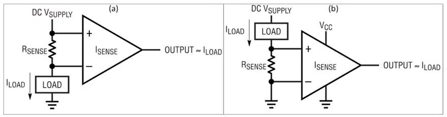
One of the standard methods used to measure load current is to insert a low-value resistor in the load line and sense the voltage across it, Figure 1, followed by an analog or digital implementation of Ohm’s Law.

RelatedPosts

Design of High Precision Integrated Resistive Voltage Dividers

TT Electronics Releases Failsafe and High Surge SMD MELF Resistors

TT Electronics Releases 100A High Power Shunt Resistors

As with many engineering decisions, the choice of what resistor value to use is a tradeoff. A higher-value resistor yields higher IR drop and voltage across its terminals, which eases voltage sensing and improves SNR.

However, it reduces power that could be going to the load, and that dissipation also contributes to resistor self-heating which brings drift and reliability concerns.

Figure 1 (a) The current-sense resistor can be placed between the power rail and load (high side) or, (b) between the load and ground (low side); high-side sensing is more difficult to implement but has significant system advantages in many cases. Source: Analog Devices

In contrast, lower-value resistors minimize this drop, but introduce accuracy and SNR issues. The lower voltage drop is also compromised by imperfections in the sense-amplifier circuit (almost always an op-amp designed for this class of application) due to input voltage offset and bias current, as well as their subsequent temperature-related drift—all of which can corrupt the sensed value beyond allowable tolerance.

In general, it’s better to use a smaller-value resistor with its lower associated voltage drop and power loss that is better overall, but only up to a point. One starting-point guideline is to size the resistor for about a 100 mV drop at maximum current. For many applications, a quick V = IR calculation puts the current-sense resistor value between one and ten milliohms. However, in lower-voltage applications, even that modest 100 mV drop, and associated dissipation, may be more than is acceptable.

Figure 2 The LRMAP3920 family of surface-mount resistors from TT Electronics measures about 5 × 10 mm and is available in values from 0.2 mΩ to 3 mΩ. Source: TT Electronics

In recent years, the availability of precision low-voltage op amps to be used to read the voltage across the sense resistor is enabling use sub-milliohm current-sense resistors. These op amps, such as the Texas Instruments TI INA185 and Analog Devices AD8417, feature an ultra-low voltage offset and bias current as well as low temperature coefficients (tempcos), and so make use of such low-ohm resistors practical.

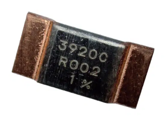
However, as with almost every advance, there’s a new set of considerations and concerns. I came across an excellent application note by TT Electronics’ Business Development Engineer Stephen Oxley. He discusses how to overcome the challenges that inherently occur when working with these low-ohmic-value current-sense resistors, Figure 2.

In his relatively modest-length and highly readable piece “Overcome the Challenges of Using Sub-Milliohm SMD,” he explains the many ways that employing these resistors is different than even milliohm-class resistors, and how they can applied inappropriately so their accuracy, consistency, and even credibility is compromised.

The app note provides three perspectives to be aware of when looking to use sub-milliohm sense-resistors:

  • How and why to consider these sub-milliohm chips as a separate class of component, rather than just lower-value versions of the milliohm versions.
  • How to avoid pitfalls during component selection and PCB layout design.
  • Ways to quantify and minimize error and variation at every stage.
Figure 3 Even the simple principle of using two resistors in parallel brings subtle layout considerations with respect to current-flow paths when using ultra-low value current sense resistors. Source: TT Electronics

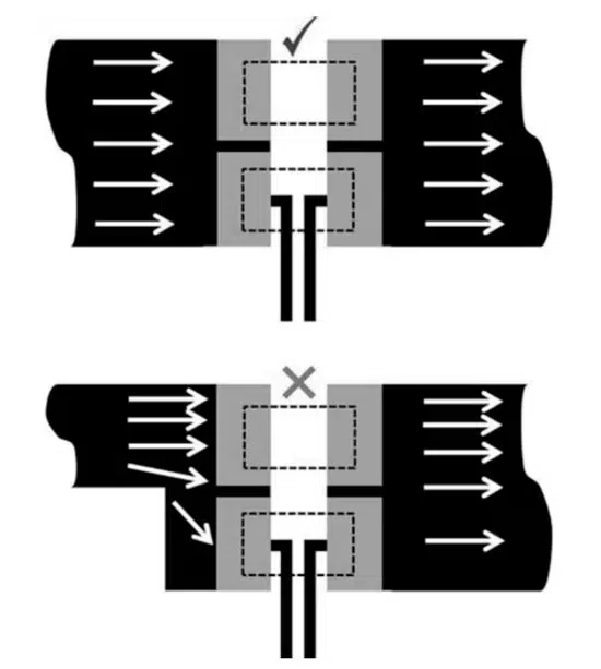
Among the many specifics are issues related to the almost mandatory use of the four-wire Kelvin connection and how subtle differences in where and how you make those connections can affect performance; anticipating and accommodating voltage differentials created by the thermoelectric effect at the junctions of dissimilar metals; current-flow paths and voltage-sensing loops of the overall sensing assembly; different  ways to use multiple resistors in parallel to lower the net resistance or increase the power-handling rating (Figure 3); and, of course, the unavoidable thermal considerations. In brief: when your sense resistor itself is sub-milliohm, the resistor-to-circuit path and contact resistance become a significant part of the story.

Note that the article is almost entirely about the resistors, materials, terminations, and current-flow paths, and has little mention of the associated electronics—and that’s another place you’ll have to work out your error budget.

Once again, what looks at first to be a simple and beneficial option, is actually laden with many subtleties along with ways to mis-apply the new component and thus negate any benefits it may offer. After all, what could be more basic than a sense resistor and Ohms law?

Worse, you could actually have inferior results and not know it, and presume your readings are accurate and consistent, only to find the signal and data are misleading. It yet again demonstrates the fact that anyone who says “that’s a simple switch to make” or “it’s all good” is either a senior, experienced engineer, or one at the other end of the expertise spectrum.

Have you ever viewed a new design or component option as an improved, beneficial alternative, only to find out later that it came with surprising downsides as well? Are these negative factors ones which you could have anticipated and better assessed by doing more homework, or were they buried deep, either deliberately or just duo to the complexity of the situation?

 Reference

  • Analog Devices, “AN-105: Current Sense Circuit Collection Making Sense of Current”

Related

Source: EDN

Recent Posts

How to Select Ferrite Bead for Filtering in Buck Boost Converter

23.10.2025
5

Power Inductors Future: Minimal Losses and Compact Designs

22.10.2025
20

Percolation Phenomenon: Degradation of Molded Power Inductors in DC/DC Converters

21.10.2025
15

Stackpole Introduces Automotive Thick Film Wide Termination Chip Resistors

20.10.2025
7

Bourns Release Automotive 4-Terminal Shunt Resistors

17.10.2025
18

Vishay Releases Automotive TO-220 Case 50W Thick Film Power Resistor

16.10.2025
14

High Energy Density Polymer Film Capacitors via Molecular and Interfacial Design

15.10.2025
25

Over-Voltage Protection Clippers, Clampers, Snubbers, DC Restorers

13.10.2025
31

Silicon Capacitors Market: Shaping the Foundation for Next-Gen Miniaturization Electronics

10.10.2025
74

Enhancing Energy Density in Nanocomposite Dielectric Capacitors

9.10.2025
41

Upcoming Events

Oct 20
October 20 - October 23

Digital WE Days 2025 – Virtual Conference

Oct 28
8:00 - 15:00 CET

Power Up Your Design: SN6507 and the Ready-to-Use Development Kit

Oct 30
11:00 - 12:00 CET

Space Ceramic Capacitors with Flexible Testing

View Calendar

Popular Posts

  • Buck Converter Design and Calculation

    0 shares
    Share 0 Tweet 0
  • Boost Converter Design and Calculation

    0 shares
    Share 0 Tweet 0
  • Flyback Converter Design and Calculation

    0 shares
    Share 0 Tweet 0
  • LLC Resonant Converter Design and Calculation

    0 shares
    Share 0 Tweet 0
  • Ripple Current and its Effects on the Performance of Capacitors

    3 shares
    Share 3 Tweet 0
  • What is a Dielectric Constant and DF of Plastic Materials?

    4 shares
    Share 4 Tweet 0
  • SEPIC Converter Design and Calculation

    0 shares
    Share 0 Tweet 0
  • Dual Active Bridge (DAB) Topology

    0 shares
    Share 0 Tweet 0
  • MLCC and Ceramic Capacitors

    0 shares
    Share 0 Tweet 0
  • Flying Capacitors

    0 shares
    Share 0 Tweet 0

Newsletter Subscription


Passive Components Blog

© EPCI - Leading Passive Components Educational and Information Site

  • Home
  • Privacy Policy
  • EPCI Membership & Advertisement
  • About

No Result
View All Result
  • Home
  • Knowledge Blog
  • PCNS

© EPCI - Leading Passive Components Educational and Information Site

This website uses cookies. By continuing to use this website you are giving consent to cookies being used. Visit our Privacy and Cookie Policy.
Go to mobile version