Passive Components Blog
No Result
View All Result
  • Home
  • NewsFilter
    • All
    • Aerospace & Defence
    • Antenna
    • Applications
    • Automotive
    • Capacitors
    • Circuit Protection Devices
    • electro-mechanical news
    • Filters
    • Fuses
    • Inductors
    • Industrial
    • Integrated Passives
    • inter-connect news
    • Market & Supply Chain
    • Market Insights
    • Medical
    • Modelling and Simulation
    • New Materials & Supply
    • New Technologies
    • Non-linear Passives
    • Oscillators
    • Passive Sensors News
    • Resistors
    • RF & Microwave
    • Telecommunication
    • Weekly Digest

    Overvoltage and Transient Protection for DC/DC Power Modules

    Choosing the Right Capacitor: The Importance of Accurate Measurements

    Littelfuse Releases TMR Switches with Ultra-Low Power Magnetic Sensing

    Skeleton Opens SuperBattery Factory in Finland 

    Kyocera Releases Ultra-Compact Low Voltage Clock Oscillators

    Murata Expands High Rel NTC Thermistors in Compact 0603M Size

    RF Inductors: Selection and Design Challenges for High-Frequency Circuits

    Wk 45 Electronics Supply Chain Digest

    Transformer Safety IEC 61558 Standard

    Trending Tags

    • Ripple Current
    • RF
    • Leakage Current
    • Tantalum vs Ceramic
    • Snubber
    • Low ESR
    • Feedthrough
    • Derating
    • Dielectric Constant
    • New Products
    • Market Reports
  • VideoFilter
    • All
    • Antenna videos
    • Capacitor videos
    • Circuit Protection Video
    • Filter videos
    • Fuse videos
    • Inductor videos
    • Inter-Connect Video
    • Non-linear passives videos
    • Oscillator videos
    • Passive sensors videos
    • Resistor videos

    Choosing the Right Capacitor: The Importance of Accurate Measurements

    RF Inductors: Selection and Design Challenges for High-Frequency Circuits

    Transformer Safety IEC 61558 Standard

    3-Phase EMI Filter Design, Simulation, Calculation and Test

    Transformer Design Optimization for Power Electronics Applications

    Common Mode Chokes Selection for RF Circuits in Next-Generation Communication Systems

    Capacitor Self-balancing in a Flying-Capacitor Buck Converter

    How to Select Ferrite Bead for Filtering in Buck Boost Converter

    Power Inductors Future: Minimal Losses and Compact Designs

    Trending Tags

    • Capacitors explained
    • Inductors explained
    • Resistors explained
    • Filters explained
    • Application Video Guidelines
    • EMC
    • New Products
    • Ripple Current
    • Simulation
    • Tantalum vs Ceramic
  • Knowledge Blog
  • Suppliers
    • Who is Who
  • PCNS
    • PCNS 2025
    • PCNS 2023
    • PCNS 2021
    • PCNS 2019
    • PCNS 2017
  • Events
No Result
View All Result
Passive Components Blog
No Result
View All Result

How to Select Ferrite Cores

9.11.2023
Reading Time: 4 mins read
A A

This article based on Sotiris Zorbas, Power Εlectronics Εngineer Frenetic newsletter will guide you through the process of choosing ferrite cores from various manufacturers and then comparing them to select the ideal core material for a specific application. 

Every Power Electronics Engineer is familiar with a couple or more manufacturers, depending on his location and degree of involvement in the field of Magnetics.

RelatedPosts

Common Mistakes in Flyback Transformer Specs

Accelerating Full Bridge LLC Resonant Converter Design with Frenetic AI

How to design a 60W Flyback Transformer

In Europe, for example, EPCOS, TDK and Ferroxcube are very popular names, thanks in part to the accessibility of their services through distributor channels like Digikey, Mouser, Farnell, TME. RS etc.

Why bother with other manufacturers?

Well, that’s an easy question: because of the price per core set and the availability when it comes to mass production. Indeed, there are some other reasons, like the tolerance with dimensions, which might be unacceptable in some designs. But really these are just exceptions.

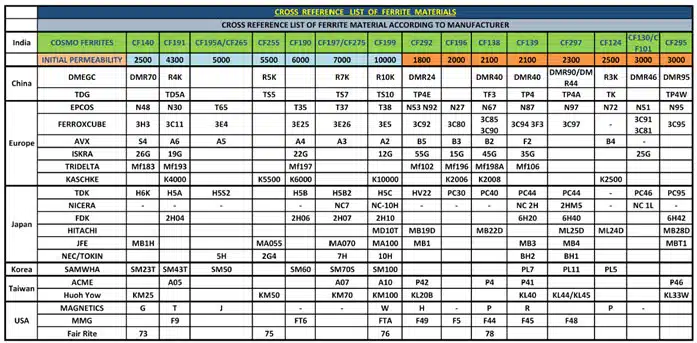
Figure 1 shows an easily available chart with part numbers of materials from different vendors that are compatible with each other. Keep in mind that this is an indicative graph, and should be treated as such.

Figure 1. Ferrite core manufacturers and materials

How should I make an informed decision about the materials?

Begin by reaching out to the manufacturer that offers the most comprehensive information about their materials. For users with access to Frenetic Online, the Core Optimizer™ tool simplifies the process of comparing these options. Currently, we provide immediate support for Ferroxcube and TDK/EPCOS materials, and you also have the flexibility to manually include other materials as needed.

 Let’s choose the least lossy material and we are done! Right?

Well, if you’re conducting a quick and basic test, then I’m ok with it. However, for a more comprehensive evaluation, the first step should be selecting a material that aligns with the operating frequency of your Converter. And that’s quite an easy task. In Figure 2 you’ll find a list of commonly used materials along with their respective recommended operating frequency ranges.

Figure 2.  Ferroxcube materials – freq. operating ranges

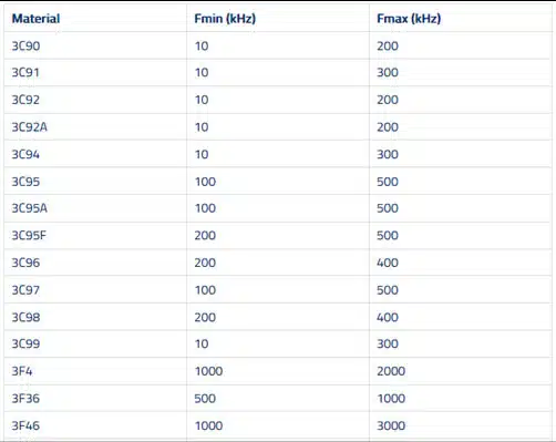
Quickly comes the realization that for a 100kHz Converter most materials are compatible. However, employing a 3F36 core at this frequency is excessive and doesn’t justify the higher cost.

As far as frequency goes, we have given the “OK” to multiple materials. It’s important to note that, while multiple materials may align with the desired frequency range, they won’t necessarily exhibit similar core losses.

Core losses and core temperature

Here is the thing, when designing a Transformer/Inductor, we usually have a core loss target in mind. If you select a material, a constant frequency and fixed flux density swing, the only thing that will affect the core losses will be the core material temperature.

Imagine a Transformer in a DC/DC Converter. You “flip” the power switch and power get transferred to the load. The Magnetic component has some thermal mass, and it will take time to reach its final temperature. 30-120min are usually enough to reach a thermal equilibrium. So, the core is initially cold. Assume an initial ambient temperature of 25°C and a final temperature of 65°C for the core. At first, the core losses will be the maximum and, as the core heats up to its final temperature, the core losses will decrease, reaching a final value.

When trying to compare losses of different materials, a good option is to think about the final temperature of the component. Of course, that’s a rough estimate, but assuming the core is at 60-80°C will get you much closer to the final value than taking into account just ambient temperature.

Table 1 provides insight into the impact of temperature on core losses across different materials. The materials are arranged from the most temperature-sensitive (3C90) to the least sensitive (3C95).

Table 1. Temperature effect on core losses for a PQ5050/100mT core set 

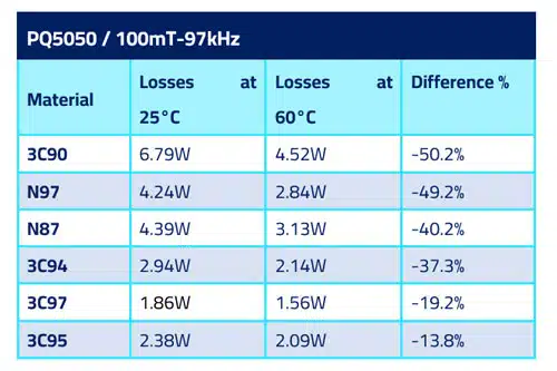
As much as 50% of core loss reduction can be observed between 25°C and 60°C for 3C90, and just 13.8% for 3C95. When looking at the power losses alone, 3C97 is the best performing material in the table.

A better approach

Next time you embark on a design, consider the impact of the target temperature under worst-case scenarios and choose the core losses accordingly. For instance, when working with a 3C94 material, aiming for a final Transformer/Inductor temperature range of 50-70°C allows for choosing approximately 35% more losses than the typical design. This can be achieved by adjusting the number of primary turns to control the operating flux swing. As the component heats up, the effect of temperature will lead to reduced core losses, bringing them closer to the initial target.

Related

Source: Frenetic

Recent Posts

Overvoltage and Transient Protection for DC/DC Power Modules

13.11.2025
23

Choosing the Right Capacitor: The Importance of Accurate Measurements

12.11.2025
41

RF Inductors: Selection and Design Challenges for High-Frequency Circuits

10.11.2025
53

Transformer Safety IEC 61558 Standard

7.11.2025
28

ESR of Capacitors, Measurements and Applications

7.11.2025
101

3-Phase EMI Filter Design, Simulation, Calculation and Test

6.11.2025
77
Image credit: Samtec

How to Match the Right Connector with Protocol Requirements

6.11.2025
20

Coilcraft Introduces Ultra-Low Loss Shielded Power Inductors

6.11.2025
26

Exxelia Presents Smart Integrated Magnetics Solution at Space Tech Expo 2025 

5.11.2025
20

Upcoming Events

Dec 2
December 2 @ 12:00 - December 4 @ 14:15 CET

Microwave Packaging Technology

Dec 9
December 9 @ 12:00 - December 11 @ 14:15 EST

Space and Military Standards for Hybrids and RF Microwave Modules

Dec 10
16:00 - 17:00 CET

Designing Qi2 Wireless Power Systems: Practical Development and EMC Optimization

View Calendar

Popular Posts

  • Buck Converter Design and Calculation

    0 shares
    Share 0 Tweet 0
  • Boost Converter Design and Calculation

    0 shares
    Share 0 Tweet 0
  • Flyback Converter Design and Calculation

    0 shares
    Share 0 Tweet 0
  • LLC Resonant Converter Design and Calculation

    0 shares
    Share 0 Tweet 0
  • Ripple Current and its Effects on the Performance of Capacitors

    3 shares
    Share 3 Tweet 0
  • Dual Active Bridge (DAB) Topology

    0 shares
    Share 0 Tweet 0
  • MLCC and Ceramic Capacitors

    0 shares
    Share 0 Tweet 0
  • SEPIC Converter Design and Calculation

    0 shares
    Share 0 Tweet 0
  • What is a Dielectric Constant and DF of Plastic Materials?

    4 shares
    Share 4 Tweet 0
  • What Electronics Engineer Needs to Know About Passive Low Pass Filters

    0 shares
    Share 0 Tweet 0

Newsletter Subscription


Passive Components Blog

© EPCI - Leading Passive Components Educational and Information Site

  • Home
  • Privacy Policy
  • EPCI Membership & Advertisement
  • About

No Result
View All Result
  • Home
  • Knowledge Blog
  • PCNS

© EPCI - Leading Passive Components Educational and Information Site

This website uses cookies. By continuing to use this website you are giving consent to cookies being used. Visit our Privacy and Cookie Policy.
Go to mobile version