Passive Components Blog
No Result
View All Result
  • Home
  • NewsFilter
    • All
    • Aerospace & Defence
    • Antenna
    • Applications
    • Automotive
    • Capacitors
    • Circuit Protection Devices
    • electro-mechanical news
    • Filters
    • Fuses
    • Inductors
    • Industrial
    • Integrated Passives
    • inter-connect news
    • Market & Supply Chain
    • Market Insights
    • Medical
    • Modelling and Simulation
    • New Materials & Supply
    • New Technologies
    • Non-linear Passives
    • Oscillators
    • Passive Sensors News
    • Resistors
    • RF & Microwave
    • Telecommunication
    • Weekly Digest

    YAGEO Releases Compact Coupled Inductors for High-Density VR Designs

    Enhancing Energy Density in Nanocomposite Dielectric Capacitors

    Advances in the Environmental Performance of Polymer Capacitors

    Vishay Releases DLA Tantalum Polymer Capacitors for Military and Aerospace

    Vishay Expanded Inductor Portfolio With More Than 2000 Stock Items 

    Paumanok Releases Capacitor Foils Market Report 2025-2030

    Modelithics Welcomes CapV as a Sponsoring MVP

    Wk 40 Electronics Supply Chain Digest

    Benefits of Tantalum Powder Stress–Strain Curve Evaluation vs Conventional Wet Test

    Trending Tags

    • Ripple Current
    • RF
    • Leakage Current
    • Tantalum vs Ceramic
    • Snubber
    • Low ESR
    • Feedthrough
    • Derating
    • Dielectric Constant
    • New Products
    • Market Reports
  • VideoFilter
    • All
    • Antenna videos
    • Capacitor videos
    • Circuit Protection Video
    • Filter videos
    • Fuse videos
    • Inductor videos
    • Inter-Connect Video
    • Non-linear passives videos
    • Oscillator videos
    • Passive sensors videos
    • Resistor videos

    Connector PCB Design Challenges

    Efficient Power Converters: Duty Cycle vs Conduction Losses

    Ripple Steering in Coupled Inductors: SEPIC Case

    SEPIC Converter with Coupled and Uncoupled Inductors

    Coupled Inductors in SEPIC versus Flyback Converters

    Non-Linear MLCC Class II Capacitor Measurements Challenges

    Percolation Phenomenon and Reliability of Molded Power Inductors in DC/DC converters

    Root Causes and Effects of DC Bias and AC in Ceramic Capacitors

    How to Calculate the Output Capacitor for a Switching Power Supply

    Trending Tags

    • Capacitors explained
    • Inductors explained
    • Resistors explained
    • Filters explained
    • Application Video Guidelines
    • EMC
    • New Products
    • Ripple Current
    • Simulation
    • Tantalum vs Ceramic
  • Knowledge Blog
  • Suppliers
    • Who is Who
  • Events
No Result
View All Result
Passive Components Blog
No Result
View All Result

How to Use a Ferrite Bead in Your Design to Reduce EMI

20.4.2022
Reading Time: 4 mins read
A A

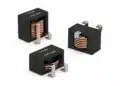
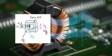
How to reduce EMI using ferrite beads? Ferrite cores can be a bit tricky, which is why it’s important to first understand the theory behind them. Most electronic components are essentially plug and play; however, ferrites have to be designed into your system. Once you know the theory, it’s time to move on to practical uses like LC filters, ground and power frequency plane separation, and source noise filtering.

Ferrite LC Filters
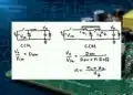
Designers are often tempted to think of ferrite beads as low pass filters. They do block high frequencies, but only in a specific band. Above that band their inherent capacitance frequency takes over. While a bead by itself can’t make a low pass filter, when combined with a bypass capacitor it can. Then you get what is essentially an LC (inductor and capacitor) filter. One major problem to look out for when using a ferrite bead like this is LC resonance.

RelatedPosts

YAGEO Releases Compact Coupled Inductors for High-Density VR Designs

Enhancing Energy Density in Nanocomposite Dielectric Capacitors

Advances in the Environmental Performance of Polymer Capacitors

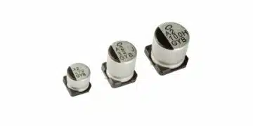
First things first, if you’re using a ferrite bead in the power supply line of your circuit you need a bypass capacitor. At low frequencies ferrite beads act as inductors, which oppose changes in current. That means if your integrated circuit is trying to draw a spike of current, the bead will resist that peak and can hinder your circuit’s operation. A bypass capacitor is needed to store up charge that can provide those power spikes. Bypass capacitors are also just a good idea in general.

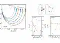
Once you have your capacitor and ferrite in place, you can start filtering out high frequencies. A ferrite bead has a couple advantages over the normal inductor used in an LC filter. Ferrite beads will give you a steeper roll-off at lower frequencies. They also have some inherent resistance, which helps dampen possible resonance frequency. While they have some damping capabilities, LC resonance can still occur. There is an especially great risk of this when using larger capacitors. If you really want to use a large capacitor, that risk can be mitigated by adding additional damping or limiting resonance in other ways. If resonance does occur, it can lead to a gain of up to 10 dB, so take care to design your filter to avoid resonance.

Mixed Signal Ground/Power Plane Connection
One of the primary ways that EMI can propagate through a circuit is through the ground and power planes. This is especially common in mixed signal circuits, where a single ground/power plane impedance is used for both analog and digital signals. It’s therefore best to have separate ground/power planes, but the grounds still need to be referenced to the same relative voltage. These problems create quite the quandary, one that ferrite beads can help solve.

Ferrite beads can be used to connect separate analog and digital ground/power planes. In this configuration, both planes are referenced to the same voltage, but are insulated from one another. A carefully chosen bead can block noise that would normally be transferred directly from one plane to another. Not every circuit should use separate ground planes connected by a ferrite bead, so check that this structure is the best for you before using it.

General Noise Filtering
Ground and power planes aren’t the only parts of your circuit that have noise problems. You also may have noise coming from digital components, a DC/DC converter, or the power line coming in. Ferrite beads can help filter out noise from all of these sources.

In the case of noisy components, you can use ferrite beads to isolate as many of them as you want to. You will presumably have bypass capacitors for each of your digital ICs, so adding ferrite beads will form the aforementioned LC filter. These filters will attenuate noise coming from the components and help keep your circuit clear of EMI.

Some analog circuits are powered by a switching DC/DC converter. You may be worried about these power supplies feeding noise into the system, but you’re probably not concerned about the analog chips sending noise out. In this case you can put a ferrite bead in line with the DC/DC converter and insulate your analog circuitry from EMI on the power rail.

You may be worried about noise coming in from outside your board. Oftentimes EMI is introduced to PCBs through their initial power source. Ferrite beads are great for filtering out that kind of high frequency noise. In fact, that’s their most common usage.

Whether your PCBs are blasting off into space or staying here on the humble Earth, they need to be protected from EMI. Ferrite beads can do that, either by attenuating a specific band of high frequencies, or acting as an LC filter when combined with a bypass capacitor. If you’re going to use a bead in an LC filter, be sure to watch out for LC resonance. You can also use ferrite beads to separate ground and power planes in mixed signal circuits, and filter out noise in general.

Related

Source: Altium

Recent Posts

YAGEO Releases Compact Coupled Inductors for High-Density VR Designs

9.10.2025
2

Enhancing Energy Density in Nanocomposite Dielectric Capacitors

9.10.2025
2

Advances in the Environmental Performance of Polymer Capacitors

8.10.2025
10

Vishay Expanded Inductor Portfolio With More Than 2000 Stock Items 

8.10.2025
7

Benefits of Tantalum Powder Stress–Strain Curve Evaluation vs Conventional Wet Test

3.10.2025
20

Electrolyte Selection and Performance in Supercapacitors

3.10.2025
17

Connector PCB Design Challenges

3.10.2025
21

Researchers Demonstrated High Energy Ceramic Capacitors Stable in Wide Temperature Range

2.10.2025
24

How to Manage Supercapacitors Leakage Current and Self Discharge 

1.10.2025
41

Experimental Evaluation of Wear Failures in SMD Inductors

1.10.2025
39

Upcoming Events

Oct 14
16:00 - 17:00 CEST

Smart Sensors, Smarter AI: Building Reliable Edge Systems

Oct 17
12:00 - 14:00 EDT

External Visual Inspection per MIL-STD-883 TM 2009

Oct 20
October 20 - October 23

Digital WE Days 2025 – Virtual Conference

Oct 21
October 21 @ 12:00 - October 23 @ 14:15 EDT

Space and Military Standards for Hybrids and RF Microwave Modules

Oct 28
8:00 - 15:00 CET

Power Up Your Design: SN6507 and the Ready-to-Use Development Kit

View Calendar

Popular Posts

  • Buck Converter Design and Calculation

    0 shares
    Share 0 Tweet 0
  • Boost Converter Design and Calculation

    0 shares
    Share 0 Tweet 0
  • Flyback Converter Design and Calculation

    0 shares
    Share 0 Tweet 0
  • LLC Resonant Converter Design and Calculation

    0 shares
    Share 0 Tweet 0
  • What is a Dielectric Constant and DF of Plastic Materials?

    4 shares
    Share 4 Tweet 0
  • Ripple Current and its Effects on the Performance of Capacitors

    3 shares
    Share 3 Tweet 0
  • Dual Active Bridge (DAB) Topology Explained

    0 shares
    Share 0 Tweet 0
  • SEPIC Converter Design and Calculation

    0 shares
    Share 0 Tweet 0
  • Flying Capacitors Explained

    0 shares
    Share 0 Tweet 0
  • MLCC and Ceramic Capacitors

    0 shares
    Share 0 Tweet 0

Newsletter Subscription


Passive Components Blog

© EPCI - Leading Passive Components Educational and Information Site

  • Home
  • Privacy Policy
  • EPCI Membership & Advertisement
  • About

No Result
View All Result
  • Home
  • Knowledge Blog
  • Premium Suppliers

© EPCI - Leading Passive Components Educational and Information Site

This website uses cookies. By continuing to use this website you are giving consent to cookies being used. Visit our Privacy and Cookie Policy.
Go to mobile version