


In this article, Vladimir Azbel Ph.D., semiconductor process reliability engineer consultant, Israel suggests control and assessment of tantalum capacitor quality by monitoring its production process, particularly the characteristics of sintered pellets.
The role of methods control in the multi-stage production process of tantalum capacitors
The tantalum capacitor (TC) quality depends on a multi-stage manufacturing process involving several stages, each tightly linked to the preceding one. Accurate control methods are necessary to ensure the reliability of the final product. In certain processes, these methods serve two purposes: maintaining the technological process and monitoring the product’s properties at a given stage, to assess its suitability for the next stage.
One of the methods used to control the sintering process is to measure the shrinkage of the tantalum anode pellet, which reflects the change in linear dimensions and, accordingly, volume. The shrinkage of a pellet made from the same powder can be used to evaluate the temperature characteristics of the sintering process. At the same time, shrinkage is used as an indicator of the suitability of pellets for the next production stage. The shrinkage of a pellet made from the same powder can be used to assess the temperature characteristics of the sintering process. Simultaneously, shrinkage is utilized as an indicator of the pellets’ suitability for the next production stage.
While pellet shrinkage reflects volume changes leading to variations in its porous structure, it does not provide details about these changes, such as neck sizes and defects that significantly impact the properties of the final pellet. These properties are crucial for meeting the next stage –formation requirements. Therefore, shrinkage does not offer essential information about the microstructure of the sintered pellet and cannot be used to evaluate its suitability for the next production stage.
The mechanical testing method is suggested for monitoring the elements of the material’s porous structure. This will enable the assessment of their behavior during the sintering process and ensure the necessary properties of the pellets for successful subsequent processing of tantalum capacitors (TC) quality product properties.
The mechanical testing method is advantageous for monitoring the porous structure of sintered pellets.
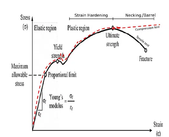
It is important to note that the sintered pellet, which is the foundation of the TC, is a product of powder metallurgy. Various techniques have been developed to control the porous structure of sintered porous products. Proposed models and mechanisms allow for the control of not only the pore volume but also the average neck size between primary powder particles, and defectiveness in the sintered tantalum pellet. These defects are mostly concentrated within the neck volume. Achieving a specific combination of these parameters allows for creating an acceptable porous structure for the next stage -formation. A mechanical testing method based on Stress-Strain curve registration (see Figure 1.) is suggested to monitor these parameters.
This method’s capabilities enable the assessment of the elements mentioned above of the porous structure in the sintered pellet, by parameters Stress-Strain curve, allowing their control during the current sintering production process and evaluating their acceptability for the subsequent production stage, which does not provide measurement shrinkage.
Experimental methodology
An experiment was conducted to investigate the benefits of using mechanical tests to control the porous structure of a sintered pellet. The researchers selected 10 pellets randomly and measured their size and weight. Then the volume and density of each pellet and determined the mean and standard deviation of the measurements. The standard deviation was approximately ~1% of the average value by volume, ~1.2% by weight, and ~1.5% by press density.
The pellets were placed in a single crucible sintering oven to reduce the impact of the sintering temperature on shrinkage. After sintering, the researchers measured the linear dimensions and mass of each pellet and calculated its volume and density. To calculate the shrinkage of each pellet, they took the average value of 10 pellets before sintering as its value before sintering.
After determining the shrinkage and density of each of the sintered pellets, they subjected them to mechanical compression tests and recorded their stress-strain curve (see Figure 1. ). From this curve, they determined Ay and calculated n. The measurement accuracy of Ay did not exceed ±5%, taking into account the measurement error of the cross-sectional area of the tablet and the testing machine.
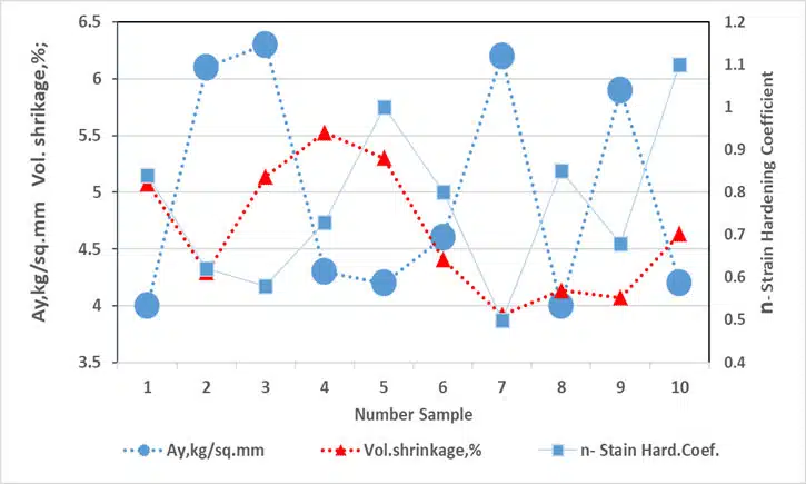
The results of shrinkage, density, Ay, and n for each of the 10 sintered pellets are presented in the figure. (see Figure 2.)
Describe characteristic Strain-Stress curve, porous material
The physical properties of a material: mechanical, electrical, etc. are determined by its structure. The structural elements of a porous material are pores, necks, and defects; and the properties themselves depend on their combination
- Yield strength (Ay) depends on the neck’s size, which affects the maximum permissible formation voltage. For porous materials, the yield stress can be calculated using the following equation: Ay = b*A0*(X/D)^2, where b is an empirical constant, Ay is the yield point of the sintered porous material, and A0 is the yield point of the deformed material. The neck size (X) is divided by the size of the primary powder particle (D), but this ratio cannot exceed 0.5.
- Young’s modulus (E) is related to porosity, which affects capacitance. The behavior of Young’s modulus of a porous material can be described using the following equation: E = E0 (1-p/pc), where E is the elastic modulus of a porous material with a porosity of the corresponding density p, and E0 is the modulus of solid material at a density pc ~ 1.
- The CC curve can be used to calculate the strain hardening coefficient (n), which is related to the defectiveness of the material. This coefficient can influence leakage currents.
Comparative Analysis: Mechanical Control vs. Shrinkage for Sintered Pellet Suitability
The results of shrinkage, density, Ay, and n measurements for 10 pellets after sintering are presented in Fig. 2. From the results, we can conclude the following:
- The shrinkage values range from 3.9% to 5.5%, and the standard deviation (STDEV) is approximately 0.6%, within the measurement accuracy.
- The values of Ay tend to divide into two groups that differ from each other by approximately 25% to 40%. The measurement error of Au is -5%.
- Changes in the values of n show an inverse relationship with Ay. of shrinkage, density, Ay, and n measurements.
Conclusion
The control and assessment of tantalum capacitor quality rely significantly on monitoring the multi-stage production process, particularly the characteristics of sintered pellets. While shrinkage measurements have been conventionally employed, this study underscores their limitations in evaluating crucial microstructural details impacting subsequent stages.
Mechanical testing, particularly Stress-Strain curve analysis, emerges as a promising alternative for scrutinizing elements like neck sizes and defectiveness, which significantly influence the properties of the final pellets.
The comparison between conventional shrinkage measurements and mechanical testing methods, for sintered pellet suitability, revealed significant insights.
Shrinkage, albeit useful to a certain extent, lacks granularity in assessing microstructural aspects crucial for subsequent processing stages.
In contrast, the mechanical testing method, specifically analyzing stress-strain curves, emerges as a superior approach. This method enables precise monitoring and evaluation of crucial parameters like yield strength (Ay) and strain hardening coefficient (n), directly reflecting the influence of microstructural elements, on the material’s properties relevant to reliability TCs.
This suggests that mechanical testing, with its capability to delve deeper into the porous structure, holds promise in augmenting the reliability and quality of tantalum capacitors. Implementing this method enhances monitoring during tantalum capacitor manufacturing, potentially addressing the limitations of traditional assessment approaches.


