Panasonic Industry’s FineX (FineCross) is a next‑generation transparent conductive film that combines high optical transmissivity with low electrical resistance for demanding EMI/EMC and radio‑wave control applications in modern display and wireless environments.
It targets design engineers who need effective electromagnetic shielding while preserving display clarity and enabling flexible, curved or non‑flat form factors.
Key features and benefits
FineX is a transparent conductive film based on an ultra‑fine copper metal‑mesh structure fabricated using Panasonic’s proprietary microfabrication technology. This metal‑mesh provides a fine, uniform wiring pattern that delivers low sheet resistance while maintaining high optical transparency, making it suitable where both EMI shielding and visibility are critical.
Key features include:
- High transmissivity thanks to ultra‑fine metal mesh wiring, supporting clear visibility in high‑resolution displays, touch screens and glass‑based HMI windows where optical performance is a priority.
- Low electrical resistance due to a high wiring aspect ratio, supporting stable current flow, fast and uniform heating in heater layers, and robust conductive paths without sacrificing transparency.
- Effective shielding without requiring a dedicated power supply or separate electrical connection to the end product, simplifying integration of the shielding layer into existing assemblies.
- Design flexibility of the copper mesh pattern, allowing complex, application‑specific geometries to tune EMI shielding performance and diffraction behavior for targeted frequency ranges and display layouts.
- Diffraction‑less design capability, reducing visual artifacts that can arise from periodic mesh structures and improving perceived display quality.
- Excellent bendability thanks to thin film‑based construction and ultra‑fine wiring, enabling application on curved, shaped or other non‑flat surfaces such as modern industrial control panels and automotive‑style HMIs.
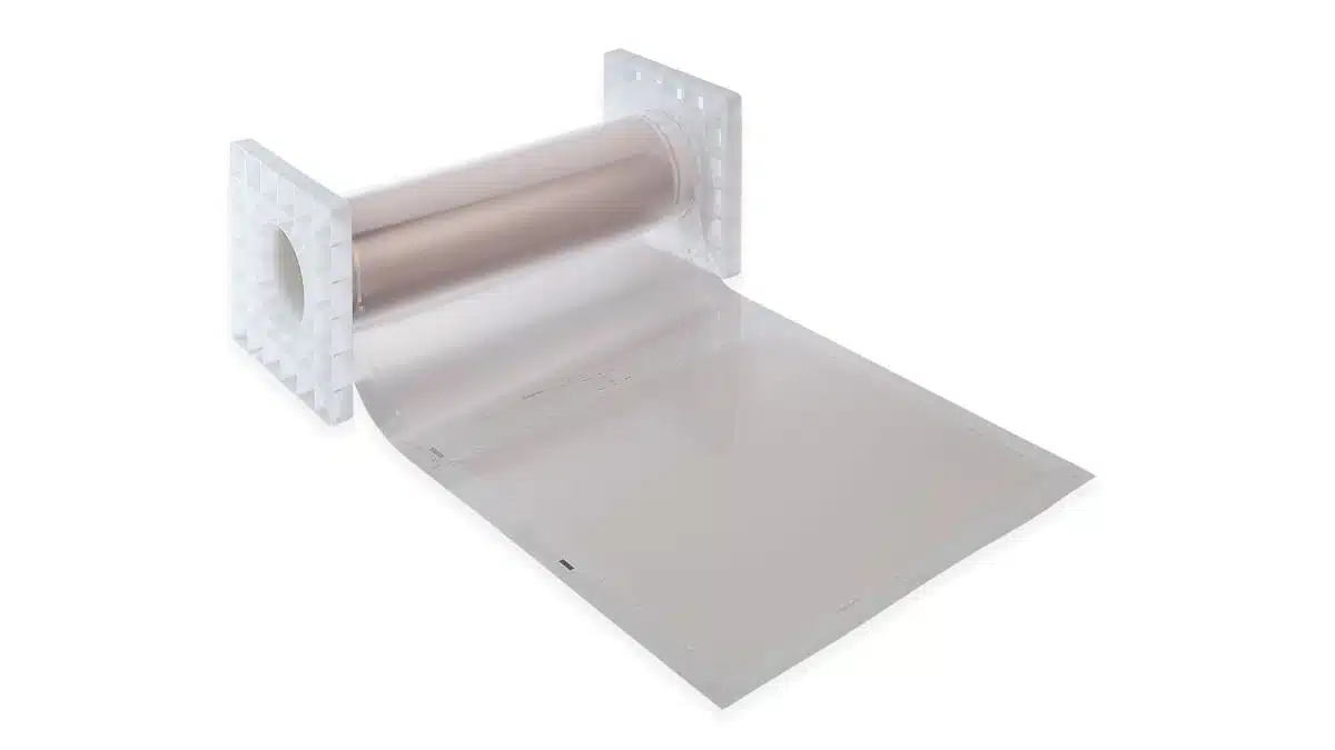
- Roll‑type film with pre‑applied Optical Clear Adhesive (OCA), arriving ready for lamination to glass or plastic substrates, which reduces process steps, lowers contamination risk and improves yield in production.
For design engineers, this combination means that a single film layer can provide optical clarity, EMI shielding, and mechanical flexibility while keeping assembly steps and stack‑up complexity under control.
Typical applications
FineX targets EMI/EMC noise shielding and radio‑wave environment control in advanced display and wireless systems where line‑of‑sight and user interaction must be preserved.
Typical use cases for noise shielding:
- Displays and monitors: Transparent EMI shielding for industrial touch screens, operator panels, medical displays, and large‑format HMI systems, where the film can be laminated to cover glass without visible patterning.
- Industrial machinery: Shielding functional windows, inspection windows, and control panel openings against high‑frequency noise from drives, inverters and switching power electronics while keeping process visibility.
Typical use cases for radio‑wave environment control:
- RFID zones: Local restriction or shaping of radio‑wave fields to improve tag detection accuracy, reduce cross‑reads, or define controlled read zones in logistics and access systems.
- Wi‑Fi and wireless systems: Anti‑interference panels or windows to optimize wireless performance in complex environments, for example to prevent leakage into sensitive areas or to limit mutual interference between co‑located wireless subsystems.
In practice, FineX is suitable anywhere a transparent barrier must control electromagnetic energy—such as in test enclosures with windows, instrument front panels, smart building glass interfaces, or machine‑vision systems with integrated displays.
Technical highlights
FineX is built around a copper metal‑mesh architecture optimized for simultaneous optical and electrical performance. The mesh uses ultra‑fine line widths and spacing with a high aspect ratio, which pushes electrical resistance down while keeping the metal coverage low enough for high transmissivity.
Important technical aspects:
- Metal‑mesh base material: Copper mesh on a transparent thin‑film substrate, combining good conductivity with established processing know‑how for mass production.
- Ultra‑fine wiring: Fine, uniform patterning to minimize visual impact and support diffraction‑less performance, which is key for high‑resolution or high‑brightness displays.
- High wiring aspect ratio: Taller, narrow conductors enable lower resistance paths without significantly increasing optical shading, supporting applications such as transparent heaters or high‑performance EMI shields.
- Thin‑film flexibility: The base film and wiring layout support bending and forming, enabling integration on curved glass, molded plastic covers, or non‑planar industrial panels.
- OCA integration: A continuous layer of Optical Clear Adhesive is pre‑laminated to the film, designed for bubble‑free bonding with controlled thickness and optical coupling.
Exact electrical and optical parameters (e.g. sheet resistance, transmissivity in percent, mesh pitch and line width, thickness and temperature range) should be taken from the official FineX datasheet for detailed design and simulation. Where precise EMI performance at specific frequencies or under particular boundary conditions is required, engineers should consult these datasheet values and, if necessary, application support.
Design‑in notes for engineers
When designing in FineX, engineers need to consider optical, electrical, mechanical and process integration aspects together to get the full benefit of the film.
Practical design‑in considerations:
- Stack‑up definition: Place FineX in the display or window stack where it can provide effective EMI shielding (e.g. bonded to the outer or inner side of cover glass) while maintaining required optical performance and touch functionality.
- Grounding strategy: Although high shielding performance can be achieved without a dedicated power supply or explicit electrical connection to the product, system‑level EMC design should still consider how the shield interacts with chassis and reference grounds for optimal performance, based on datasheet guidance and EMC test results.
- Optical performance: Check total transmissivity and haze in combination with other layers (cover glass, polarizers, touch sensors) to ensure that contrast and color reproduction meet system requirements.
- Display resolution and diffraction: For high‑PPI or fine‑pixel‑pitch displays, pay attention to potential moiré or diffraction effects; FineX’s mesh is designed to achieve diffraction‑less behavior, but final validation should be done with the target display type.
- Mechanical integration: Use FineX where bending radius and forming conditions are within the limits specified by the manufacturer, especially for curved or 3D‑formed panels, to avoid cracking of the mesh or delamination.
- Process compatibility: Align lamination parameters (pressure, temperature, speed, cleanliness) with the OCA’s recommended process window to avoid bubbles, voids or optical defects, and to maintain long‑term adhesion.
- Environmental and reliability testing: Include FineX in standard environmental tests (temperature cycling, humidity, vibration, UV exposure where relevant) to confirm stability of optical clarity, adhesion, and electrical continuity over the intended lifetime.
For EMC simulation work, engineers can treat FineX as a transparent conductive layer characterized by its sheet resistance and optical transmittance; these parameters can then be used in field simulations to estimate shielding effectiveness SE across relevant frequency bands, with final tuning done in hardware using representative assemblies.
Source
This article is based on information provided by Panasonic Industry Europe’s official product introduction of the FineX transparent conductive film and associated downloadable materials, interpreted and contextualized for design engineers and component purchasers.