Passive Components Blog
No Result
View All Result
  • Home
  • NewsFilter
    • All
    • Aerospace & Defence
    • Antenna
    • Applications
    • Automotive
    • Capacitors
    • Circuit Protection Devices
    • electro-mechanical news
    • Filters
    • Fuses
    • Inductors
    • Industrial
    • Integrated Passives
    • inter-connect news
    • Market & Supply Chain
    • Market Insights
    • Medical
    • Modelling and Simulation
    • New Materials & Supply
    • New Technologies
    • Non-linear Passives
    • Oscillators
    • Passive Sensors News
    • Resistors
    • RF & Microwave
    • Telecommunication
    • Weekly Digest

    CMSE 2026 Announces Call for Presentations on High-Reliability Military and Space Electronics

    ESA Call for Papers 6th Space Passive Component Days – SPCD 2026

    Würth Elektronik Offers Halogen‑Free EMC Gaskets for Displays and Housings

    Component Distribution Supply Chain January 2026

    Binder Unveils M8 Flange Solder Connectors for Flexible Cabling

    Power Electronics Tools for Passives and Magnetic Designs

    Modelithics Releases Component Model Library for SIMULIA CST Studio Suite

    Exxelia Publishes Micropen White Papers for Printed Electronics

    Stackpole Releases AlN High‑Power Thick Film Chip Resistors

    Trending Tags

    • Ripple Current
    • RF
    • Leakage Current
    • Tantalum vs Ceramic
    • Snubber
    • Low ESR
    • Feedthrough
    • Derating
    • Dielectric Constant
    • New Products
    • Market Reports
  • VideoFilter
    • All
    • Antenna videos
    • Capacitor videos
    • Circuit Protection Video
    • Filter videos
    • Fuse videos
    • Inductor videos
    • Inter-Connect Video
    • Non-linear passives videos
    • Oscillator videos
    • Passive sensors videos
    • Resistor videos

    One‑Pulse Characterization of Nonlinear Power Inductors

    Thermistor Linearization Challenges

    Coaxial Connectors and How to Connect with PCB

    PCB Manufacturing, Test Methods, Quality and Reliability

    Transformer Behavior – Current Transfer and Hidden Feedback

    Choosing the Right Capacitor: The Importance of Accurate Measurements

    RF Inductors: Selection and Design Challenges for High-Frequency Circuits

    Transformer Safety IEC 61558 Standard

    3-Phase EMI Filter Design, Simulation, Calculation and Test

    Trending Tags

    • Capacitors explained
    • Inductors explained
    • Resistors explained
    • Filters explained
    • Application Video Guidelines
    • EMC
    • New Products
    • Ripple Current
    • Simulation
    • Tantalum vs Ceramic
  • Knowledge Blog
  • DossiersNew
  • Suppliers
    • Who is Who
  • PCNS
    • PCNS 2025
    • PCNS 2023
    • PCNS 2021
    • PCNS 2019
    • PCNS 2017
  • Events
No Result
View All Result
Passive Components Blog
No Result
View All Result

Intel® Enpirion® Expand its Digital PowerSoC Integrated Modules

26.8.2020
Reading Time: 7 mins read
A A

Intel Enpirion PowerSoC modules are DC-DC step-down converters that integrate nearly all the components needed to build a power supply without sacrificing performance or efficiency. These solutions are designed to meet strict FPGA, ASIC, and processor power requirements.

A DC-DC step-down power converter can be designed in several configurations, ranging from discrete to modular architectures depending on the level of integration. As shown in Figure 1, the primary elements of a step-down DC-DC converter include the gate drive circuity, power inductor, output voltage feedback loop, and control circuitry. These components can be integrated at various levels to create different power management devices. 

RelatedPosts

NIC Components Extends SMD High Voltage MLCC Offering

Stackpole Offers RoHS Compliant Lead-Free Thick Film Chip Resistors

Smiths Interconnect’s SMD Power Resistors with Heat Sink Qualified to Space Flights

Components of a DC-DC Step-Down Switching Converter
Figure 1. Components of a DC-DC step-down switching converter
Level of Integration by device (From Left to Right: Completely Discrete, Regulator/Partially Discrete, PowerSoC)
Figure 2. Level of integration by device from left to right: completely discrete, regulator/partially discrete, PowerSoC.

There are many ways that power companies integrate these elements to create different semiconductor devices. These devices can remain completely (100%) discrete, consisting of a standalone controller, standalone power stage, inductor, and passive components. These components can also be fashioned into a regulator, a slightly more integrated device, consisting of an integrated controller and power stage with an external inductor and passive devices. 

Both fully and partially discrete power management solutions have some external components. The architectures of both options can be difficult to design in, particularly for non-power experts, as control loop compensation and stability analysis can be challenging. Additionally, the inductor is one of the largest components in the converter, so placing it externally dramatically increases the total solution size. However, one of the benefits of designing with a partially discrete architecture is that they offer a balance of integration and flexibility. 

Intel Enpirion PowerSoC
Figure 3. Intel Enpirion PowerSoC

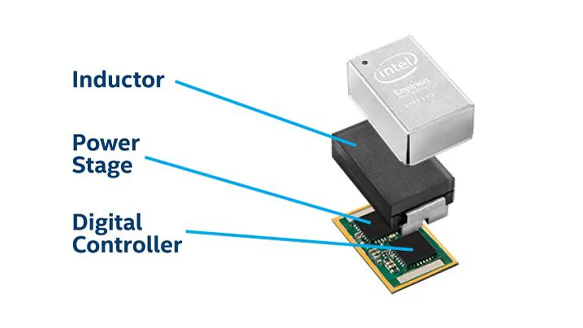
In contrast to fully or partially discrete implementations, Intel offers a completely integrated power module, the PowerSoC. These DC-DC step-down converters integrate the PWM control, gate drive circuitry, MOSFET switches, inductor, and control loop compensation components. Intel PowerSoCs only require a few external passive components for filtering, and occasionally for control loop compensation. The PowerSoC is the most integrated step-down DC-DC converter semiconductor solution, offering several design and system advantages.

Intel Enpirion PowerSoCs are a reasonable choice for customers seeking a power module or high-value regulator socket.  PowerSoCs are particularly valuable for systems requiring small solution size, power density, ease of use, low risk, low noise, and maximum time to prototyping or production. 

PowerSoCs are Intel’s largest power converter offering, including >50 devices. The Intel range of PowerSoCs includes low power, performance-optimized and highly efficient, 12V Input, and digital families. 

Table 1. Intel’s Range of PowerSoC Families

EP53xx & EN53xxSmall & Low Power
EN63xxPerformance-optimized & Highly Efficient
EN23xx & EN29xx12V Input
EM21xxDigital

Technical Advantages of Using Enpirion PowerSoCs

Thermal Derating

Thermal de-rating is when a power converter cannot deliver the full rated output current at high temperatures due to silicon and device design limitations without risking damage. For example, if a customer needs to use a device near peak output current and their system needs to operate above ~45°C, they may need to use a larger power supply to reach sufficient current. 

In general, Intel Enpirion PowerSoCs do not require thermal de-rating, while most other modules require moderate to extreme thermal de-rating. 

Power Density

Power Density describes how much power a module can deliver, in the smallest footprint, without thermal issues – combining small solution size and efficiency. Intel Enpirion devices nearly always have superior power density compared to competing converter solutions available.

For example, the Intel EM2130 power density for a 12V to 1V conversion at 30A is as follows:

IOUT = 30A (no thermal derating!) → POUT = 30A*1V = 30W

Total Solution Size ~18 mm x 20 mm = 360 mm2 = 0.56 in2

Total Power Density = >53W/in2!

Because of PowerSoC’s high level of integration, including inductor integration, they require a much smaller PCB (printed circuit board). In contrast, discrete power solutions can take up to 7x more area than an Intel PowerSoC. This small footprint allows system designers to reduce the size of their system PCB and save on cost. Designers may even be able to move to a smaller form factor.

In addition, a 16-layer printed circuit board with blind and buried vias, as required by many advanced systems today, costs approximately $15 per square inch (2.3 cents per square millimeter) – so saving even a small amount of space delivers meaningful cost reductions. Designers can also take advantage of the extra PCB space by adding features or additional components to make the end solution more competitive. 

Noise (Ripple and EMI) 

In general, power supply noise can refer to either conducted electrical noise (ripple) or radiated electromagnetic noise (EMI). 

Ripple, or conducted electrical noise, is the small, unwanted variation on Vout due to energy transfers during the on/off cycles of any switching converter. Ripple can conduct through the PCB and cause unwanted behavior, such as jitter or signal traces, which is particularly detrimental for noise sensitive circuits (eg SERDES). Ripple is largely generated by design choices regarding switching frequency and the parasitic capacitance and inductance. Intel Enpirion PowerSoCs feature high switching frequencies and high integration to minimize parasitic capacitance and inductance, enabling Enpirion devices to have very low ripple – less than 10 mV for most devices.  

EMI, or electromagnetic noise, originates from high rates of current changes (di/dt) flowing in loops, creating a loop antenna. EMI can cause unwanted behavior such as data or audio interference, or even violate regulatory limits set by the FCC. Radiated power is proportional to the radius of the current loop and decreases by r^8. PowerSoCs have current loops with a much smaller radius, r, than discrete solutions, ensuring the radiated power is significantly lower. 

Reliability (FIT Rate)

A key measure of system reliability and robustness is the Failures in Time rate, or FIT rate. 

One FIT = One failure per billion hours, so lower FIT rates are better.

The FIT rate of a power converter is the sum of all the component FIT rates, which is the sum of the controller FIT rate, power MOSFET fit rates, inductor FIT rate, and FIT rate of all the necessary passive components. 

Discrete power solutions, by definition, are numerous components from multiple vendors assembled by a system designer. While each semiconductor and passive component is tested by the manufacturer, the total reliability of the complete discrete power solution depends entirely on how the system is designed, and what components are selected. 

In contrast, Intel PowerSoCs integrate most key components needed in a step-down converter. This essentially complete power supply system, in an integrated circuit package, is validated by the supply manufacturer as a total solution, ensuring that PowerSoCs will have lower FIT rates. 

Review of PowerSoC Advantages

In conclusion, Intel PowerSoCs offer: 

  • Turnkey solutions that are designed and validated as a complete power system, requiring little power expertise
  • Saved design time and effort, accelerating time to market
  • A low-risk solution that prevents time-consuming design error
  • Integration into a small total footprint

While PowerSoCs tend to have less design flexibility and can be more costly than fully or partially discrete solutions, it is important to understand the total value of a power module. To do so, designers must understand the total cost they pay for when using a power module versus a discrete power solution. When discussing pricing, consideration of the additional design, testing, and validation time should be evaluated.

Ultimately, the net development cost to design a discrete power supply is often higher than the development cost for designing with a PowerSoC, which should be considered when choosing your power management solution. This means that Intel Enpirion PowerSoCs may be cheaper for customers in low to mid-range volumes, where Intel offers the best balance of performance value and ASP.  

Related

Source: Intel

Recent Posts

CMSE 2026 Announces Call for Presentations on High-Reliability Military and Space Electronics

28.1.2026
10

ESA Call for Papers 6th Space Passive Component Days – SPCD 2026

28.1.2026
10

Würth Elektronik Developed a Custom Transformer for Active Hand Orthosis

26.1.2026
34

Passive Components in Quantum Computing

22.1.2026
116

Exxelia Offers Custom Naval Transformers and Inductors

21.1.2026
16

Würth Elektronik Introduces Product Navigator for Passive Components

14.1.2026
87

Panasonic Passive Components for Reliable Robotic Arms

14.1.2026
113

DC/DC Push‑Pull Converter vs PSFB Design Guide

12.1.2026
133

How Metal Prices Are Driving Passive Component Price Hikes

8.1.2026
432

Upcoming Events

Feb 24
16:00 - 17:00 CET

Designing Qi2 Wireless Power Systems: Practical Development and EMC Optimization

Mar 3
16:00 - 17:00 CET

Cybersecurity at the Eleventh Hour – from RED to CRA – Information and Discussion

Mar 21
All day

PSMA Capacitor Workshop 2026

View Calendar

Popular Posts

  • Buck Converter Design and Calculation

    0 shares
    Share 0 Tweet 0
  • Boost Converter Design and Calculation

    0 shares
    Share 0 Tweet 0
  • LLC Resonant Converter Design and Calculation

    0 shares
    Share 0 Tweet 0
  • Flyback Converter Design and Calculation

    0 shares
    Share 0 Tweet 0
  • Ripple Current and its Effects on the Performance of Capacitors

    3 shares
    Share 3 Tweet 0
  • How Metal Prices Are Driving Passive Component Price Hikes

    0 shares
    Share 0 Tweet 0
  • MLCC and Ceramic Capacitors

    0 shares
    Share 0 Tweet 0
  • Dual Active Bridge (DAB) Topology

    0 shares
    Share 0 Tweet 0
  • What is a Dielectric Constant and DF of Plastic Materials?

    4 shares
    Share 4 Tweet 0
  • Degradation of Capacitors and its Failure Mechanisms

    0 shares
    Share 0 Tweet 0

Newsletter Subscription


Passive Components Blog

© EPCI - Leading Passive Components Educational and Information Site

  • Home
  • Privacy Policy
  • EPCI Membership & Advertisement
  • About

No Result
View All Result
  • Home
  • Knowledge Blog
  • PCNS

© EPCI - Leading Passive Components Educational and Information Site

This website uses cookies. By continuing to use this website you are giving consent to cookies being used. Visit our Privacy and Cookie Policy.
Go to mobile version