Passive Components Blog
No Result
View All Result
  • Home
  • NewsFilter
    • All
    • Aerospace & Defence
    • Antenna
    • Applications
    • Automotive
    • Capacitors
    • Circuit Protection Devices
    • electro-mechanical news
    • Filters
    • Fuses
    • Inductors
    • Industrial
    • Integrated Passives
    • inter-connect news
    • Market & Supply Chain
    • Market Insights
    • Medical
    • Modelling and Simulation
    • New Materials & Supply
    • New Technologies
    • Non-linear Passives
    • Oscillators
    • Passive Sensors News
    • Resistors
    • RF & Microwave
    • Telecommunication
    • Weekly Digest

    Smolteks CNF MIM Capacitor Break 1 µF/mm²

    Samsung Electro-Mechanics Releases 0201 X7T 1uF 6.3V MLCC for ADAS Applications

    Murata Announces 0402 Automotive Chip Ferrite Beads for V2X

    2025 Thick and Thin Film Resistor Networks Environment Overview

    Role of High-Q Ceramic Filters to Overcome GNSS Jamming

    Optimization of IoT for GEO NB-NTN Hybrid Connectivity

    TDK Releases Automotive Power-Over-Coax Inductor for Filters

    Advanced Conversion Announces Mass Production of 200C Film Capacitors

    VinaTech Supercapacitors: Enhancing Smart Meter Reliability and Efficiency

    Trending Tags

    • Ripple Current
    • RF
    • Leakage Current
    • Tantalum vs Ceramic
    • Snubber
    • Low ESR
    • Feedthrough
    • Derating
    • Dielectric Constant
    • New Products
    • Market Reports
  • VideoFilter
    • All
    • Antenna videos
    • Capacitor videos
    • Circuit Protection Video
    • Filter videos
    • Fuse videos
    • Inductor videos
    • Inter-Connect Video
    • Non-linear passives videos
    • Oscillator videos
    • Passive sensors videos
    • Resistor videos

    Understanding Switched Capacitor Converters

    Coupled Inductors Circuit Model and Examples of its Applications

    Inductor Resonances and its Impact to EMI

    Highly Reliable Flex Rigid PCBs, Würth Elektronik Webinar

    Causes of Oscillations in Flyback Converters

    How to design a 60W Flyback Transformer

    Modeling and Simulation of Leakage Inductance

    Power Inductor Considerations for AI High Power Computing – Vishay Video

    Coupled Inductors in Multiphase Boost Converters

    Trending Tags

    • Capacitors explained
    • Inductors explained
    • Resistors explained
    • Filters explained
    • Application Video Guidelines
    • EMC
    • New Products
    • Ripple Current
    • Simulation
    • Tantalum vs Ceramic
  • Knowledge Blog
  • Suppliers
    • Who is Who
  • Events
No Result
View All Result
Passive Components Blog
No Result
View All Result

Introduction to EMI Filtering

2.5.2025
Reading Time: 8 mins read
A A

This blog article by Knowles Precision Devices introduces EMI Filtering, EMI Filter, how it works and what is its performance.

With the ever-increasing use of electronic equipment comes a greater likelihood of interference from all the other equipment out there. In the same vein, we’re seeing more circuits, with lower power levels, that are easily disturbed; so, there’s a need to protect equipment from EMI (electromagnetic interference). In automotive or medical applications, for example, there can be no false alarms due to external interference. The level of uncertainty has pushed EMI compliance testing to the component level.

RelatedPosts

Role of High-Q Ceramic Filters to Overcome GNSS Jamming

Knowles Extends Range and Performance of C0G MLCC Capacitors

Supercapacitors Benefits in Industrial Valve Fail-Safe Control Systems

To meet international legislation such as the EU Directive on EMC or the FCC, EMI filtering is an essential element of equipment design. Introducing screening measures to case or cables, for example, may suffice in many instances, but you might need to introduce low-pass filtering for additional protection as well. Here, we will begin to explore EMI filtering and the terminology used in designing effective protection.

Input / Output Cabling

Figure 1: Modes of propagation of EMI

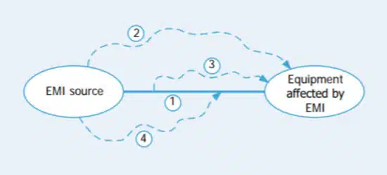
In an ideal situation, a Faraday Cage would protect a piece of equipment or circuit from EMI by totally enclosing it in a metal (or conductive box) and preventing interference. However, most pieces of equipment require input and/or output connections for power cables or signal control lines. The cables providing these kinds of connections can act as antennae that can pick up interference and radiate it, see Figure 1.

Subsequently, the following can occur:

  • Interference can enter a piece of equipment directly through the cabling (conducted interference).
  • Radiated interference can travel directly to the affected equipment.
  • Interference can exit an EMI source via a cable, subsequently to be radiated from the cable and to the affected equipment.
  • Interference can be radiated from an EMI source and then picked up by a cable entering the affected equipment.

Filter Location

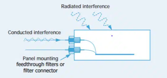
Filter Location matters when it comes to preventing interference entering or leaving a piece of equipment. With Panel Mount Filters, feedback through EMI filters can be mounted in the wall of a shielded case, see Figure 2. All incoming or outgoing cables would then pass through the filters. Power, or any other wanted signals, pass through the filters unaffected, whereas higher frequency interference is removed. The screened case protects against radiated interference, and feedthrough filters protect against conducted interference. Combined, the integrity of the equipment is assured.

Figure 2: Feedthrough filters remove conducted interference and provide ultimate performance
Figure 3: Surface mount filters remove conducted interference, performance reduced due to radiated interference

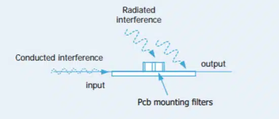
When there is no suitable bulkhead for mounting filters, Surface Mount Filters, see Figure 3, are an effective option. In general, insertion loss performance is reduced at higher frequencies, unless additional screening measures are taken. Thoughtful design practices including short tracks and connections, good grounding, and proximity to input will help improve insertion loss performance.

Common Terms

The following chart provides a foundational understanding of common terms used when designing and implementing EMI filters.

Conducted Interference Interference transmitted along a conductor/cable.Protection is provided by a series component. If a feedthrough filter is used to remove conducted interference, and mounted in the wall of a shielded compartment, it provides effective filtering while maintaining the screening integrity. It should be noted that the filter will reduce both emissions and susceptibility.
Cut-off Frequency/3dB pointThe frequency at which filters start to become effective.Generally taken to be at the 3dB point of the attenuation curve. Anything on the line below this frequency will be unaffected. The higher the capacitance of the filter the lower the cut-off, and vice versa. It will also vary depending on source and load impedances.
EMCElectromagnetic compatibility.A situation wherein two pieces of electrical or electronic equipment are able to function in the same environment without adversely affecting, or being affected by, each other.
EMIElectromagnetic interference.A broad term covering a wide range of electrical disturbances, natural and man-made, from dc to GHz frequencies and beyond. Sources of disturbance may include radar transmitters, motors, computer clocks, lightning, electrostatic discharge and many other phenomena.
Conducted EmissionsSignals, unwanted (interference) or otherwise from a piece of equipment.
Radiated InterferenceInterference transmitted in free air.Protection is provided by shielding, but if filters are not used to protect against conducted emissions, the unfiltered lines can act as aerials radiating interference outside the shielded cage.
SusceptibilityThe extent to which a piece of equipment is vulnerable to interference emitted from another piece of equipment.
ESDElectrostatic discharge.ESD can result in damage through excessive voltage spikes. We can assist on whether our products can meet specific ESD test requirements.
Insertion LossAt a given frequency, the insertion loss of a feedthrough suppression capacitor or filter connected into a given transmission system.Defined as the ratio of voltages appearing across the line immediately beyond the point of insertion, before and after insertion. As measured herein, insertion loss is represented as the ratio of input voltage required to obtain constant output voltage, with and without the component, in the specified 50Ω system. This ratio is expressed in decibels (dB) as follows:

insertion loss knowles

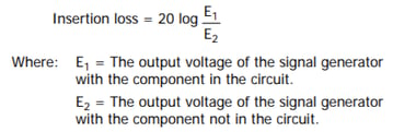
When testing is conducted with a network/spectrum analyzer, the equipment usually maintains a constant output voltage and can be set to record the output to input voltage ratio in decibels.
Low-Pass FilterA filter that lets through dc and low frequency signals, while attenuating (unwanted) high frequency noise.
Panel MountA panel mounted filter that will pass the signal from one side of the wall of a shielded box (or ‘Faraday Cage’) to the other (it feeds the signal through the panel).For effective operation, the filter input and output should be screened from each other, i.e. there should ideally be no apertures in the panel.
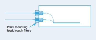
panel mounting knowles
Surface Mount FilterSurface Mount Filter A filter that is suitable for surface mounting on PCBs.It offers improved filtering compared to standard MLCCs, ease of assembly and savings on board space compared to a combination of discrete filter elements. Filter performance at higher frequencies is reduced compared to panel mount types, unless additional shielding measures are taken.
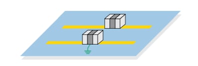
surface mount filter
Working VoltageContinuous operating voltage.This can potentially be across the entire operating temperature range.
X2Y FilterIntegrated passive component with extremely low self inductance for filtering and de-coupling.

For filtering applications: filtering applications

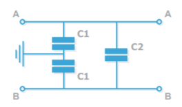
For de-coupling applications: de-coupling applications

Related

Source: Knowles Precision Devices

Recent Posts

Role of High-Q Ceramic Filters to Overcome GNSS Jamming

19.6.2025
3

Bourns Introduces 1206 Multilayer Common Mode Filters

16.6.2025
7

Smoltek CNF-MIM Capacitor Commercialization Update

11.6.2025
29

Understanding Switched Capacitor Converters

9.6.2025
70

What Track Width To Use When Routing PCB

6.6.2025
30

Capacitance Definition of Non-Linear Voltage Dependent Capacitors

5.6.2025
34

Bourns Releases New SMD Line Filter for Enhanced EMI Suppression

4.6.2025
16

TDK Expands 3-terminal Automotive SMD Chip Filters to 35V

4.6.2025
19

Coupled Inductors Circuit Model and Examples of its Applications

21.5.2025
132

Würth Elektronik Introduces LTspice Models for ESD Products

21.5.2025
68

Upcoming Events

Jun 24
16:00 - 17:00 CEST

Limitations of PSFB converters and improvements by a variable inductor ft. Sam Ben-Yaakov

Jun 24
17:00 - 18:00 CEST

Ultra-Compact and Efficient Switched-Capacitor Power Converters

Jul 23
13:00 - 14:00 CEST

PCB design for a Smartwatch

View Calendar

Popular Posts

  • Buck Converter Design and Calculation

    0 shares
    Share 0 Tweet 0
  • Boost Converter Design and Calculation

    0 shares
    Share 0 Tweet 0
  • Flyback Converter Design and Calculation

    0 shares
    Share 0 Tweet 0
  • What is a Dielectric Constant and DF of Plastic Materials?

    4 shares
    Share 4 Tweet 0
  • LLC Resonant Converter Design and Calculation

    0 shares
    Share 0 Tweet 0
  • Ripple Current and its Effects on the Performance of Capacitors

    3 shares
    Share 3 Tweet 0
  • How to Design an Inductor

    0 shares
    Share 0 Tweet 0
  • SEPIC Converter Design and Calculation

    0 shares
    Share 0 Tweet 0
  • Dual Active Bridge (DAB) Topology Explained

    0 shares
    Share 0 Tweet 0
  • Flying Capacitors Explained

    0 shares
    Share 0 Tweet 0

Newsletter Subscription


Passive Components Blog

© EPCI - Leading Passive Components Educational and Information Site

  • Home
  • Privacy Policy
  • EPCI Membership & Advertisement
  • About

No Result
View All Result
  • Home
  • Knowledge Blog
  • Premium Suppliers

© EPCI - Leading Passive Components Educational and Information Site

This website uses cookies. By continuing to use this website you are giving consent to cookies being used. Visit our Privacy and Cookie Policy.
Go to mobile version