


This article summarizes a technical webinar delivered by power electronics consultant Nicola Rosano, who walked engineers through the entire LLC transformer design workflow using the Frenetic Collect simulation platform, from circuit fundamentals to validated physical schematics.
The LLC resonant converter is one of the most efficient isolated DC–DC topologies in use today, but its transformer demands careful co-design of magnetising inductance, leakage inductance, and core selection.
Key Takeaways
- Nicola Rosano’s webinar outlines the LLC Transformer design workflow using the Frenetic Collect platform, emphasizing co-design of magnetising and leakage inductance.
- LLC Transformers require careful handling of constraints like zero-voltage switching and minimal core losses, traditionally demanding extensive manual calculations.
- The Frenetic Collect platform accelerates design processes by allowing input of standard parameters and generating graphical representations for quick validation.
- Case studies demonstrate design techniques, including the advantages of matrix transformers for improved thermal management and scalability.
- The upcoming integration of planar magnetics support aims to further enhance design efficiency for modern power converter architectures.
Why LLC Transformer Design Is Non-Trivial
A well-designed LLC transformer must simultaneously satisfy several competing constraints: it must achieve zero-voltage switching (ZVS) on the primary side, zero-current switching (ZCS) at the secondary rectifier, minimise core losses across the operating frequency range, and keep winding temperatures within limits. Traditional manual approaches rely on iterative spreadsheet calculations and bench iterations that can take days or even weeks.
The LLC circuit itself evolved from the simpler LC series resonant converter. By placing a sufficiently large inductor in parallel with the load — physically realised as the transformer’s magnetising inductance — designers obtain the three-element LLC kernel. The parallel-to-series transformation then allows the parallel load to be moved into series with the smaller leakage inductance, yielding the classic LLC tank. Understanding this derivation is important because it explains why the ratio of magnetising inductance to leakage inductance (commonly denoted as the inductance ratio) is the single most critical parameter controlling voltage gain shape and soft-switching margins.
The LLC Kernel Circuit and Switching Behaviour
The LLC kernel circuit exhibits two natural resonant frequencies. Operating between these two frequencies is the standard design strategy, as this region guarantees both ZVS and ZCS simultaneously — the foundation of high-efficiency operation.
Key behavioural characteristics of the LLC kernel:
- ZVS zone: The primary switches turn on with zero voltage, eliminating turn-on switching losses. This is achievable when the converter operates above the series resonant frequency.
- ZCS zone: The secondary rectifier diodes or synchronous switches commutate at zero current, eliminating reverse-recovery losses.
- Operating point A vs. operating point B: At the series resonant frequency (point A), impedance is at its maximum and circulating currents are minimised — the most efficient operating point. Point B, below resonance, offers lower impedance and higher circulating currents, representing a less favourable condition that should be avoided under normal load.
Core loss analysis reinforces the preference for operating near point A. At higher impedance the flux density excursion in the core is well controlled, whereas operation closer to the parallel resonant frequency increases flux density and pushes core loss up disproportionately.
Scaling Laws: Rapid Design Adaptation Across Power and Frequency
One of the most practically useful concepts covered in the webinar is the application of scaling laws to LLC transformer design. Once a reference LLC kernel has been characterised — with its inductance ratio, voltage gain curve, and switching boundaries established — the same design can be scaled to different voltage levels, power ratings, and switching frequencies without restarting the design process from scratch.
The scaling approach works as follows:
- Identify the frequency scaling factor based on the ratio of the target switching frequency to the reference kernel frequency.
- Identify the power scaling factor based on the ratio of the target power level to the reference kernel power.
- Apply both factors to rescale inductance values, turns ratios, and core geometry.
This methodology is particularly valuable in product families where a single converter architecture needs to cover multiple power classes, for example 500 W, 1 kW, and 2 kW variants sharing the same resonant tank structure. The graphical approach to working-point selection, combined with scaling laws, allows engineers to confirm ZVS and ZCS preservation at the new operating point before committing to physical design.
Frenetic Collect Platform: Workflow and Key Features
The Frenetic Collect platform is a browser-based, model-driven simulation environment for magnetic component design. The webinar demonstrated how the platform reduces a multi-day manual design exercise to a workflow measurable in minutes.
Input Parameter Entry
The platform accepts the standard LLC specification set as direct inputs:
- Input voltage range and nominal operating voltage
- Output voltage and rated output power
- Target switching frequency range (minimum, nominal, maximum)
- Turns ratio
- Inductance ratio (ratio of magnetising inductance to leakage inductance)
- Step-load profile: a secondary power field allows engineers to simulate the transformer behaviour at off-nominal load conditions without re-entering the full design
Graphical Design Approach
A graphical normalised gain chart is generated automatically from the entered parameters. The chart overlays ZVS and ZCS boundary curves on the voltage-gain versus normalised frequency plane, making it straightforward to verify that the selected operating point lies within the safe soft-switching region. This visualisation eliminates the need to manually solve the transcendental equations associated with LLC gain analysis.
Simulation and Validation
Before committing to core selection, the platform validates the electrical design via SPICE-compatible simulation (demonstrated with TINA cross-verification in the webinar). Engineers are advised to correctly map the input inverter stage — full-bridge or half-bridge — since the effective drive voltage seen by the resonant tank differs by a factor of two between these configurations. Output rectification can be specified as full-bridge or centre-tap (four-wave), each carrying different implications for secondary winding current stress and output capacitor ripple.
Validation steps embedded in the platform include:
- Confirmation of ZVS and ZCS at nominal and worst-case load
- Waveform inspection of primary current and voltage to identify any hard-switching events
- Core loss estimation using flux density swing and the applicable loss model for the chosen material
Core Optimiser
Once the electrical design is validated, the Core Optimiser module suggests candidate core geometries and materials based on the loss and thermal constraints entered. The suggestion considers:
- Required energy-handling capability (related to inductance and peak current)
- Target operating frequency (which governs core material selection — ferrite grades optimised for 100 kHz differ significantly from those suited to 500 kHz or above)
- Thermal budget and permissible temperature rise
The result is a ranked list of suitable cores with preliminary winding turn counts, giving engineers a starting point for physical layout.
Mechanical Design Integration
The platform generates detailed transformer schematics including bobbin layout, winding layer stackup, and interleaving recommendations. This output bridges the gap between the electrical simulation and the manufacturing drawing, reducing the number of design-transfer errors between the electronics team and the magnetics supplier.
Case Study 1: Standard LLC Transformer Design
The first design example demonstrated in the webinar targeted a conventional wound transformer for an LLC converter. The design objective was to maintain both ZVS and ZCS across the specified load range while keeping core losses at a minimum.
Key design decisions illustrated:
- Selecting the inductance ratio to shape the gain curve appropriately for the input voltage range
- Using the scaling law to adjust leakage inductance from an initial value to a revised value (for example, shifting from 100 µH toward 143 µH as power increases) while simultaneously adjusting magnetising inductance to preserve the inductance ratio — in this instance maintained at six
- Verifying that reducing the inductance ratio slightly when moving to higher power levels is an acceptable trade-off that keeps the converter within soft-switching boundaries
The one-page LLC design calculation summary generated by the platform provides all key parameters in a single view, which the presenter recommended keeping as a reference document throughout the design review process.
Case Study 2: Matrix Transformer Design
The second example moved beyond the conventional single-core approach to a matrix transformer topology — an arrangement where the primary winding is shared across multiple smaller cores, each contributing a fraction of the total secondary turns.
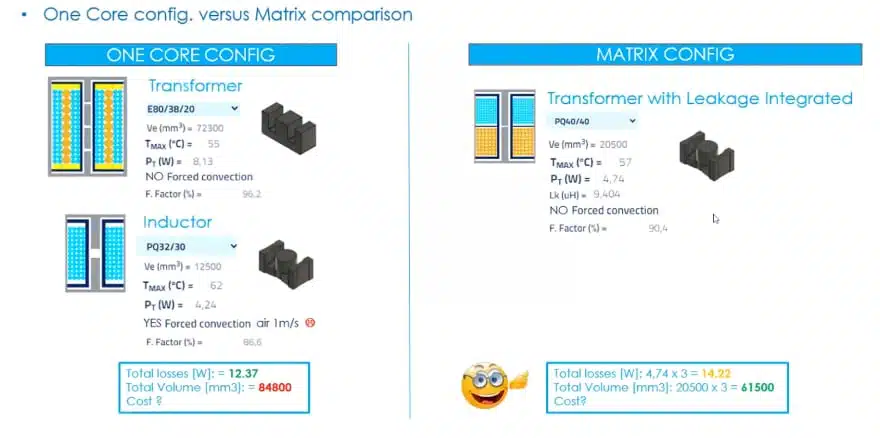
Advantages demonstrated for the matrix topology:
- Symmetry: Equal flux distribution across multiple cores reduces the risk of core saturation caused by winding asymmetries or DC bias.
- Reduced parasitics: Shorter winding paths on each individual core lower leakage inductance contributed by the transformer structure itself, giving the designer tighter control over the resonant tank elements.
- Improved thermal management: Heat is distributed across multiple cores and multiple secondary winding sections, reducing hot-spot temperatures and improving long-term reliability.
- Scalability: Adding or removing core sections allows power scaling without a complete transformer redesign.
The matrix approach is increasingly adopted in high-power LLC converters used in EV on-board chargers, data-centre power supplies, and bidirectional energy storage interfaces, where both power density and thermal performance are critical.
CLLC Extension: Bidirectional Converter Support
A notable platform addition highlighted at the start of the webinar is the CLLC premium feature. The CLLC topology extends the LLC converter by adding a mirrored resonant tank on the secondary side, enabling bidirectional power flow with soft switching in both directions. This makes it directly applicable to:
- Vehicle-to-grid (V2G) and vehicle-to-home (V2H) on-board chargers
- Battery energy storage systems requiring charge and discharge control
- Bidirectional DC–DC conversion stages in microgrids
The Frenetic platform’s CLLC simulation module handles the additional complexity of the symmetrical resonant tank, including gain curve analysis for both power-flow directions.
Planar Magnetics Integration: Upcoming Feature
At the time of the webinar, integration of planar transformer support was described as being in beta testing, with a full platform release expected in the first quarter of the following year. Planar transformers — built using PCB windings rather than conventional wire — are preferred in applications requiring extremely low profile, high reproducibility, and tight leakage inductance control. Their integration into the Frenetic workflow would allow the same graphical design methodology to be applied directly to PCB-based magnetics, further compressing the design cycle.
Design-In Notes for Engineers
Practical recommendations that emerge from the webinar content:
- Define the inductance ratio early. The ratio of magnetising to leakage inductance determines the entire gain curve shape. Changing it late in the design process requires re-evaluation of core selection and winding layout.
- Validate with SPICE before ordering cores. The platform’s cross-verification against TINA or equivalent SPICE simulators is not optional — it catches mapping errors in the input inverter stage (full-bridge vs. half-bridge) that otherwise produce factor-of-two errors in the effective tank excitation voltage.
- Use the step-load field. Entering an off-nominal power level in the secondary power field allows the platform to flag any degradation in soft-switching margins under light-load or step-load transient conditions.
- Apply scaling laws before starting a new design. If a related design exists in the team’s archive, deriving the new specification from a validated kernel via scaling laws is faster and reduces the risk of errors compared to starting from a blank sheet.
- Consider the matrix topology for powers above approximately 1–2 kW. The thermal and parasitic benefits become significant at higher power densities and are particularly relevant for automotive and industrial applications with strict thermal budgets.
- Plan for CLLC from the outset if the application involves bidirectional power flow. Retrofitting bidirectionality into a unidirectional LLC transformer design is difficult; addressing it at the topology selection stage avoids costly redesigns.
How to Design an LLC Transformer Using Frenetic Simulator
- Step 1: Define the LLC specification
Gather and enter all key converter parameters into the Frenetic platform: input voltage range, output voltage, rated output power, target switching frequency range, and required turns ratio. Also specify the input inverter configuration (full-bridge or half-bridge) and the output rectifier type (full-bridge or centre-tap), as these directly affect the effective voltage applied to the resonant tank.
- Step 2: Set the inductance ratio
Choose the ratio of magnetising inductance to leakage inductance. Use the graphical gain chart generated by the platform to verify that the selected ratio produces a gain curve that covers the required input voltage range with adequate margin. The operating point must lie within the region where both ZVS and ZCS are simultaneously guaranteed.
- Step 3: Apply scaling laws if adapting an existing design
If a validated LLC kernel exists for a related design, calculate the frequency scaling factor and the power scaling factor relative to the reference kernel. Use these to rescale inductance values and confirm that the new operating point preserves soft-switching conditions before proceeding to core selection.
- Step 4: Validate the electrical design with SPICE simulation
Before committing to a physical core, run the built-in SPICE cross-verification (for example via TINA). Check primary current and voltage waveforms for any hard-switching events. Use the optional step-load power field to verify soft-switching margins under off-nominal load conditions.
- Step 5: Run the Core Optimiser
Submit the validated electrical parameters to the Core Optimiser module. Review the ranked list of candidate ferrite cores based on energy-handling capability, operating frequency, and thermal budget. Select the most appropriate core for the application, taking into account availability and cost if relevant.
- Step 6: Generate the mechanical schematic
Use the platform’s Mechanical Design Integration output to produce the full transformer schematic, including bobbin layout, winding layer stackup, turn counts per layer, and interleaving recommendations. This document serves as the manufacturing specification passed to the magnetics supplier or in-house winding team.
- Step 7: Verify the final design against requirements
Cross-check the output schematic against the original specification: confirm turns ratio, inductance values, and estimated core and winding losses. If the design target is a matrix transformer, verify symmetry across all core sections and review the distributed thermal model before sign-off.
Conclusion
LLC resonant converters remain a benchmark topology for isolated DC–DC conversion wherever high efficiency and low EMI are priorities — from server power supplies and EV on-board chargers to industrial power stages and bidirectional energy storage systems. The transformer sits at the heart of the LLC tank, and its design directly determines whether the converter achieves the intended soft-switching margins, thermal headroom, and power density.
The workflow demonstrated by Nicola Rosano through the Frenetic Collect platform shows that the gap between a validated specification sheet and a ready-to-build transformer schematic can be closed in a fraction of the time required by conventional manual methods. The graphical gain-curve approach makes the relationship between inductance ratio, operating frequency, and switching boundaries immediately visible, removing the need to solve complex transcendental equations by hand. The built-in SPICE cross-verification step adds a necessary layer of confidence before any physical prototype is committed to.
Scaling laws extend the value of each validated design kernel across entire product families, making the approach particularly attractive for teams managing multiple power variants from a common platform. The addition of matrix transformer support within the same environment further broadens the scope, addressing the thermal and parasitic challenges that arise as power levels rise.
Looking ahead, the planned integration of planar magnetics design and full CLLC simulation will make the platform relevant to an even wider range of modern power converter architectures. For design engineers and magnetics specialists working under schedule pressure, model-driven tools of this type represent a practical path to shortening development cycles without compromising on design quality.
Further read:
- Designing a 2 kW LLC Transformer with Integrated Resonant Inductor
- LLC Resonant Converter Design and Calculation
FAQ
An LLC transformer is a magnetic component designed specifically for the LLC resonant converter topology. Unlike a standard transformer, it intentionally uses its magnetising inductance as part of the resonant tank circuit and its leakage inductance as the series resonant inductor. These two inductances, together with the external resonant capacitor, form the three-element LLC network that enables zero-voltage switching on the primary and zero-current switching on the secondary.
The inductance ratio is the ratio of the magnetising inductance to the leakage inductance of the LLC transformer. It is the single most critical parameter shaping the voltage gain curve of the converter. A higher inductance ratio produces a narrower gain curve with less frequency variation under load, which simplifies control design. A lower ratio widens the gain curve, offering more range but increasing circulating currents and conduction losses. Selecting the correct inductance ratio early in the design process is essential because changing it later requires re-evaluation of core selection and winding layout.
Zero-voltage switching (ZVS) means the primary switches turn on when the voltage across them is zero, eliminating capacitive turn-on losses. Zero-current switching (ZCS) means the secondary rectifier diodes or synchronous switches commutate when the current through them is zero, eliminating reverse-recovery losses. Together, ZVS and ZCS are responsible for the high efficiency of LLC converters — typically above 96–98% in optimised designs. Maintaining both conditions across the full load range is the primary objective of LLC transformer design.
Frenetic Collect is a browser-based, model-driven simulation platform for designing high-frequency magnetic components including LLC transformers. It accepts standard LLC specifications as inputs, generates a graphical normalised gain chart to confirm soft-switching margins, performs SPICE-compatible electrical validation, and then runs a Core Optimiser to suggest suitable ferrite cores and winding geometries. The platform outputs a detailed mechanical schematic suitable for manufacturing handover, compressing a multi-day manual design process into a workflow of minutes.
Scaling laws allow a validated LLC design kernel to be adapted to different power levels, operating frequencies, or voltage levels without restarting the design from scratch. By calculating a frequency scaling factor and a power scaling factor relative to the reference kernel, engineers can directly derive new inductance values, turns ratios, and approximate core geometry while preserving the original soft-switching boundaries. This is particularly useful in product families that share a common resonant tank architecture across multiple power variants.
A matrix transformer distributes the total primary winding across multiple smaller cores, each contributing a portion of the secondary turns. The advantages over a single-core design include better thermal distribution (lower hot-spot temperatures), reduced leakage inductance per core section (tighter control of resonant tank elements), improved symmetry (lower risk of core saturation from winding asymmetries), and easier scalability to higher power. Matrix transformers are particularly suited to LLC converters operating above approximately 1–2 kW, such as EV on-board chargers, data-centre power supplies, and bidirectional energy storage converters.
Source
The information in this article is based on a recorded webinar produced by Frenetic and presented by Nicola Rosano (BSc, MSc Electrical Engineering), an independent consultant in power electronics. The original video is available on the Frenetic YouTube channel and was also published on the Passive Components Blog. No specifications have been extrapolated beyond what was directly demonstrated or stated in the source material.
References
- Frenetic webinar – Design an LLC Transformer Easily in Frenetic Simulator with Nicola Rosano (YouTube)
- Original article on Passive Components Blog
- Frenetic supplier page on Passive Components Blog
- Related article: Designing a 2 kW LLC Transformer with Integrated Resonant Inductor
- Related article: Standard vs Planar LLC Transformers Comparison for Battery Chargers