


Galvanic isolation is a cornerstone of safe and robust power electronics design, ensuring that circuits can exchange signals or power without allowing unintended current flow between them. It forms the safety barrier between hazardous voltages and users, and it decouples ground domains to mitigate interference and ground loops.
This article based on Würth Elektronik’s webinar video “Mastering Galvanic Isolation: Ensuring Safety in Power Electronics with Würth Elektronik products” explains the underlying standards, defines key insulation metrics, and compares major isolation technologies such as optocouplers, digital isolators, transformers, power modules, and capacitors.
The objective is to provide design engineers with a practical decision framework: when a particular isolation type is suitable, which standards apply, how clearance and creepage must be treated, and how electronic components can be integrated into equipment certified to IEC 62368-1.
Key Takeaways
- Galvanic Isolation separates circuits to prevent unintended current flow and protect against hazardous voltages.
- Key motivations include user safety, ground loop separation, and interference-free data transmission.
- Popular applications span industrial automation, power supplies, and smart metering systems.
- Various isolation types exist: functional, basic, double, and reinforced, each with specific safety features.
- Integration into IEC 62368-1 requires understanding isolation components and applicable standards for device certification.
Key points
- Galvanic isolation separates electrical circuits so that no direct or unintended current can flow between them while signals or power can still be exchanged.
- Typical motivations are user protection from hazardous voltages, separation of ground loops, reduction of common-mode interference, and interference-free data transmission.
- Primary application clusters are industrial automation interfaces (CAN, SPI, RS-232, RS-485), power supplies and converters (UPS, solar inverters, lighting), and smart metering/EV charging.
- Standards split into basic safety publications (e.g., IEC 60664-1), component standards (optocouplers, digital isolators, transformers, capacitors), and device standards such as IEC 62368-1.
- Isolation types include functional (no shock protection), basic (single barrier), double (basic plus second independent barrier), and reinforced (single robust barrier equivalent to double in protection).
- Key geometry metrics are clearance (shortest air path), creepage (shortest surface path), and distance through isolation (dielectric thickness), all driven by voltage and pollution conditions.
- Practical isolation methods: optical (optocouplers), capacitive (digital isolators and capacitors), and inductive (transformers and isolated power modules).
- Optocouplers are well suited for low-channel, lower data-rate applications such as feedback in isolated converters; digital isolators target space-constrained, multi-channel, high‑speed interfaces.
- Isolated power modules used here are functionally isolated and not suitable as safety isolation against hazardous voltages.
- IEC 60747‑17 is used for Würth Elektronik digital isolators because it provides the most stringent basic and reinforced isolation testing, including long‑term (30‑year) reinforced isolation guarantees.
Background and motivation
The working definition describes galvanic isolation as the separation of electrical circuits so that no direct or unintended current can flow between them while signals or power may still be exchanged. This separation is critical wherever hazardous voltages are present, or where different ground potentials and strong disturbances must not propagate through the system.
The main motivations:
- Safety barrier between hazardous voltages and the user.
- Separation of ground loops between spatially distributed circuits.
- Minimization of common-mode interference.
- Interference-free data transmission across domains.
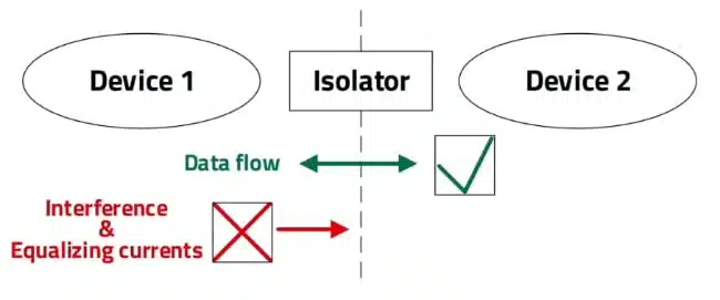
A simplified block diagram illustrates two devices connected via an isolator: data passes through the isolation barrier, while interference and potential equalization currents are blocked. This abstraction applies to many real systems, from industrial fieldbuses to power converter feedback loops.
Application domains
Three major application clusters are emphasized:
- Industrial automation: interfaces such as CAN, SPI, RS‑232, and RS‑485, where sensor nodes, actuators, and controllers often operate at different potentials.
- Power supplies and converters: UPS systems, telecom power supplies, solar inverters, and lighting power supplies, which must protect users and low-voltage control electronics from mains and high‑voltage domains.
- Smart metering and EV chargers: systems combining measurement, communication, and power stages with strict safety and EMC requirements.
In each domain, the isolation solution must simultaneously satisfy electrical safety, signal integrity, and system‑level EMC targets.
Standards landscape
The webinar structures the standards landscape into three layers: basic safety publications, component standards, and device standards.
- Basic safety publications – exemplified by IEC 60664‑1 – condense general safety principles and guidelines over a wide application range. They define core parameters such as required clearance and creepage distances for given working voltages and pollution degrees.
- Component standards are specific to individual component classes: resistors, capacitors, inductors, transformers, digital isolators, and optocouplers each have their own documents. These specify dielectric test voltages, insulation system classification, and mechanical constraints.
- Device standards such as IEC 62368‑1 address complete devices or sub‑assemblies consisting of many components. Equipment must ultimately be evaluated and certified at this level.
IEC 60664‑1 acts as the foundation referenced by both component and device standards. It harmonizes the interpretation of concepts such as clearance, creepage, and distance through isolation, and it provides the baseline isolation voltage requirements.
Types of isolation
To simplify the standard terminology for design practice, there are four main isolation types.
- Functional isolation: Ensures correct circuit operation but offers no protection against electric shock; the user must never be able to touch functional isolation points.
- Basic isolation: Provides a single insulation barrier sufficient to protect against electric shock under normal operation.
- Double isolation: Combines basic isolation with an additional, independent insulation layer so that a single fault does not remove protection.
- Reinforced isolation: Realized as one robust insulation system equivalent in protective performance to double isolation, for example the large plastic block around mains plug pins.
A key reason why basic isolation is often not sufficient is the one‑failure analysis: a crack or fault in a single basic barrier can remove protection, necessitating double or reinforced isolation for many safety‑relevant applications.
Clearance, creepage, and distance through isolation
Three geometric parameters govern the physical realization of insulation:
- Clearance is the shortest distance through air between two conductive parts, such as PCB traces. It determines how much potential difference can be withstood before air breaks down and a flashover discharge occurs.
- Creepage is the shortest path along the surface of an insulating material between conductive parts. It accounts for surface degradation, contamination, humidity, and tracking effects.
- Distance through isolation is the minimum thickness of insulation material between conductive parts, often the dielectric thickness inside an IC or transformer.
Violating clearance can lead to ionization of air and a conductive path across the gap, while insufficient creepage may cause surface tracking, especially in polluted or humid environments.
Comparison of isolation methods
Galvanic isolation can be realized optically, capacitively, or inductively. Each method has specific characteristics, trade‑offs, and applicable standards.
Comparison table: isolation technologies
| Isolation method | Physical principle | Typical use case | Isolation type potential | Key advantages | Key limitations / caveats |
|---|---|---|---|---|---|
| Optocoupler | LED emits light to photodetector across gap | Isolated converter feedback, low‑channel interfaces | Safety barrier possible | Simple, robust, analog or digital signaling | LED aging, limited data rate, CTR drift |
| Digital isolator | High‑frequency modulation across capacitor | SPI/ADC isolation, high‑speed digital buses | Safety barrier possible | High data rate, multi‑channel, compact | Needs careful CMTI/EFT assessment, IC‑level integration |
| Isolated power module | HF transformer transfers power across barrier | Isolated supply rails (e.g. RS‑485 transceiver supply) | Functional isolation only | Fully integrated DC/DC, easy to use | Not suitable for electrical safety barrier vs. mains |
| Transformer | Magnetic induction between primary/secondary | SMPS isolation, safety power transformers | Safety barrier possible | High power transfer, robust insulation systems | Bulkier, requires more design effort for EMC and safety |
| Capacitor (X/Y, PCB) | AC coupling across dielectric, blocks DC | EMI filtering, line‑to‑earth Y caps, stitching caps | Safety barrier with Y | Filters plus isolation, PCB‑integrated possible | Must meet Y‑cap rules; acts as isolation bridge in 62368‑1 |
Optocouplers
Optocouplers consist of an internal LED on the input side and a photodetector on the output side, separated by an optical gap, which serves as the isolation barrier. When the LED is driven, it emits infrared light that the detector converts to an electrical signal on the isolated side.
A canonical use case is tight output voltage regulation in an isolated converter. The analog output voltage on the secondary side is sampled by a divider and error amplifier, then transmitted across the barrier via the optocoupler to the primary‑side controller for pulse‑width modulation control.
Due to their design, optocouplers can:
- Provide a safety barrier between hazardous voltages and the user.
- Separate ground loops between spatial circuits.
- Reduce common‑mode interference and support interference‑free data transmission.
They also support analog transmission, as shown in the feedback example.
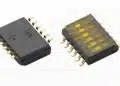
Digital isolators
Digital isolators use a capacitive isolation barrier fabricated in a CMOS process. A modulator converts the input signal into a high‑frequency carrier that passes through the capacitor; a receiver on the other side demodulates it back to a logic signal at outputs A and B.
A typical application is isolation of an SPI interface between an ADC located at a high‑voltage measurement point and a low‑voltage microcontroller. The isolator sits between the ADC and MCU, providing the signal barrier while allowing fast synchronous communication.
Like optocouplers, digital isolators can provide:
- A safety barrier between hazardous voltages and users.
- Ground loop separation.
- Minimization of common‑mode interference and interference‑free data transmission.
Würth Elektronik digital isolators are certified according to IEC 60747‑17, which the speaker characterizes as the harshest testing standard for basic and reinforced isolation. It requires destructive tests and ongoing sampling from production for re‑testing until failure, and it is notable for guaranteeing reinforced isolation performance for 30 years—a guarantee not typically stated in other standards.
When to choose optocouplers vs digital isolators
The practical rule of thumb for selection:
- Prefer digital isolators when:
- Board space is limited.
- A high channel count is required.
- High data rates are needed (e.g., tens to hundreds of megabits per second).youtube+1
- Prefer optocouplers when:
- Space is not critical.
- Data rates are low.
- Only one or two channels are necessary.youtube+1
There is an overlap region where either technology may work; in those cases, all system requirements—including EMC, analog vs digital signaling, aging, and cost—must be considered holistically.
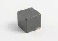
Isolated power modules
Isolated power modules are fully integrated DC/DC converters that transfer energy across a galvanic barrier using a high‑frequency transformer. Primary and secondary windings are magnetically coupled but electrically separated.
A typical example is an isolated RS‑485 interface: optocouplers may isolate the data path, while an isolated power module provides an isolated supply for the transceiver, so both power and signals are galvanically separated from the microcontroller domain.
However, the Würth Elektronik power modules discussed are only functionally isolated and thus not suitable for providing electrical safety against hazardous voltages. They can separate ground loops and mitigate common‑mode interference but must not be treated as basic or reinforced isolation against mains.
Transformers
Transformers provide galvanic isolation by transferring electrical energy between circuits through magnetic induction, with primary and secondary completely electrically separated by the isolation system. In the converter example, the transformer not only transfers power but also realizes power isolation between primary and secondary sides.
Transformers can be designed and certified to provide:
- Safety barriers between hazardous voltages and users.
- Separation of ground loops.
- Minimization of common‑mode disturbances.
- Support for interference‑free data transmission when combined with appropriate circuitry.
In IEC 62368‑1, transformers come with explicit information on their type of isolation (basic, reinforced, or double). Designers can use IEC 62368‑1 clause 5.4, which covers insulation materials and requirements, to integrate the transformer’s insulation data into the overall equipment evaluation.
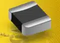
Capacitors and stitching capacitance
Capacitors enable galvanic isolation by allowing AC or transient signals to pass while blocking DC current, thanks to two conductive plates separated by a dielectric. In isolation contexts, X and Y safety capacitors are used in the primary side of power supplies—between line and neutral, and between line or neutral and protective earth—for EMC filtering.
In safety terms, Y‑capacitors can bridge an isolation barrier between line and earth, and standards like IEC 62368‑1 specify cases where a minimum of two Y capacitors in series is required to achieve reinforced isolation. Capacitors also play a role as PCB‑integrated components; stitching capacitors are realized by overlapping PCB layers configured as capacitor plates.
Unlike transformers, capacitors themselves do not always carry a clear “type of isolation” label such as basic or reinforced. Instead, IEC 62368‑1 provides an Annex (referred to as Annex G in the webinar) that describes how such components must be evaluated and integrated into the equipment-level isolation assessment.youtube+1
Integration into IEC 62368‑1 equipment
A central design task is integrating various isolation components—capacitors, transformers, optocouplers, and digital isolators—into a device certified according to IEC 62368‑1.
Key points:
- Capacitors and optocouplers can be treated similarly: since they may not explicitly specify “functional/basic/reinforced” isolation in their own standards, the designer must use the IEC 62368‑1 Annex on components (referred to as Annex G) together with clearance, creepage, and test voltage data to determine the isolation category in the end product.
- Transformers often include explicit information about their isolation type. Designers can directly map transformer data to IEC 62368‑1 requirements via the clauses on insulation materials and electric strength tests.
- Digital isolators implemented as semiconductor devices can be integrated using IEC 62368‑1 clauses relating to solid insulation in semiconductors and electric strength tests, coupled with the isolator’s own standard (IEC 60747‑17) for CMTI and electric strength.
The presented integration slide shows that for every Würth Elektronik ISO component family, there is a clear route to bring its isolation characteristics into the unified IEC 62368‑1 evaluation of the complete application.
Recommended comparison table: isolation type vs. use case
| Isolation type | Shock protection | Fault tolerance (single fault) | Typical use in equipment |
|---|---|---|---|
| Functional | No | None | Internal functional barriers, non‑touchable parts |
| Basic | Yes (normal use) | None | Some low‑risk circuits, internal separations |
| Double | Yes | Yes | Hand‑held or user‑accessible mains products |
| Reinforced | Yes | Yes (single robust system) | Mains input, chargers, safety-critical equipment |
Suggested Decision Flow for Isolator Selection
- Is a safety barrier against hazardous voltages required?
- If no: functional isolation (e.g., some power modules, stitching capacitors) may suffice.
- Is high data rate and/or high channel count required?
- If yes: consider digital isolators.
- Is analog transmission or classic SMPS feedback needed?
- If yes: optocouplers preferred.
- If no: transform/combination of digital isolators and transformers may be used.
Conclusion
This paper has outlined the role of galvanic isolation in protecting users and systems from hazardous voltages, mitigating interference, and enabling reliable data transmission in power electronics. It has connected practical application domains with the underlying IEC standards and the key physical metrics of clearance, creepage, and distance through isolation.
Engineers can now differentiate between functional, basic, double, and reinforced isolation; select appropriate technologies such as optocouplers, digital isolators, transformers, power modules, and capacitors; and understand how to integrate these components into devices certified to IEC 62368‑1. Typical use cases include isolated feedback in switched‑mode power supplies, isolated industrial fieldbus interfaces, and safe primary–secondary separations in smart metering and charging infrastructure.
Galvanic Isolation in Power Electronics – FAQ
Galvanic isolation is the separation of electrical circuits so that no direct or unintended current can flow between them, while signals or power can still be exchanged across an isolation barrier. It protects users from hazardous voltages and prevents ground loops and common-mode interference in complex power and control systems.
Galvanic isolation provides a defined insulation barrier between hazardous and touchable circuits, helping to prevent electric shock and fire hazards under normal operation and single-fault conditions. In standards such as IEC 62368-1, basic, double, and reinforced isolation levels are used to ensure that equipment remains safe even if one insulation layer fails.
Functional isolation supports correct circuit operation but is not intended to protect users against electric shock. Basic isolation is a single insulation barrier that provides shock protection in normal operation. Double isolation combines basic insulation with a second independent layer to remain safe under a single fault. Reinforced isolation is a single, robust insulation system that provides protection equivalent to double isolation, often used at mains interfaces and in user-accessible equipment.
IEC 60664-1 defines fundamental safety concepts such as clearance, creepage, and distance through insulation for given voltages and pollution degrees. Component-level standards cover optocouplers, digital isolators, transformers, and capacitors, while IEC 62368-1 governs complete devices and equipment. Digital isolators from Würth Elektronik, for example, are tested according to IEC 60747-17, which specifies stringent requirements for basic and reinforced isolation over long lifetimes.
Optocouplers use an internal LED and a photodetector separated by an optical gap and are well suited for analog feedback and low-data-rate, low-channel-count applications such as isolated SMPS feedback. Digital isolators use high-frequency modulation across a capacitive barrier and are optimized for high data rates, multiple channels, and compact layouts, making them ideal for isolating SPI, ADC, and other fast digital interfaces.
solated power modules discussed in the article are functionally isolated DC/DC converters that separate ground domains and reduce interference, but they are not rated as basic or reinforced isolation against hazardous voltages. They can be used to generate isolated supply rails, for example in an RS-485 interface, but must not be relied on as the primary electrical safety barrier.
Clearance is the shortest distance through air between conductive parts and determines the voltage at which air can break down and cause flashover. Creepage is the shortest path along the surface of an insulating material and must account for contamination, humidity, and tracking. Distance through isolation is the minimum thickness of solid insulation between conductors. All three must be dimensioned according to voltage rating, pollution degree, and the applicable insulation type defined in the relevant safety standards.
How to choose and implement galvanic isolation in a power electronics design
- Step 1 – Define safety and isolation requirements
Determine whether your design must protect users from hazardous voltages or only separate functional domains. Specify the required insulation type (functional, basic, double, or reinforced), working voltage, overvoltage category, and pollution degree according to IEC 60664-1 and the applicable product standard such as IEC 62368-1.
- Step 2 – Identify interfaces and power paths that cross the isolation barrier
List all signal interfaces (for example SPI, CAN, RS-485, ADC inputs) and power paths that must cross the isolation barrier. Decide which side is hazardous (primary) and which side is SELV or user-accessible (secondary), and document all required data rates, channel counts, and analog versus digital signal characteristics.
- Step 3 – Select the appropriate isolation technology
Use a decision flow: if you need a safety barrier and high data rate or many channels, prefer digital isolators. If data rate is low and channels are few or analog feedback is required, optocouplers are often a better fit. Use transformers for power transfer and safety isolation on the primary–secondary boundary, and functionally isolated power modules where only ground separation and EMC benefits are required.
- Step 4 – Dimension clearance, creepage, and insulation distances
For the chosen components, verify the required clearance, creepage, and distance through insulation using IEC 60664-1 tables and your working voltage and pollution degree. Lay out the PCB so that air gaps and surface distances between conductors meet or exceed these values, and respect any minimum distances and isolation test voltages specified in the component datasheets.
- Step 5 – Integrate isolation components according to IEC 62368-1
Map each isolation component to the correct clauses in IEC 62368-1. Use Annex G to integrate capacitors and optocouplers that do not explicitly state isolation type, and clause 5.4 for transformers with defined basic, double, or reinforced insulation. For digital isolators, combine IEC 60747-17 component-level data with the solid insulation and electric strength test requirements of IEC 62368-1.
- Step 6 – Verify performance, EMC, and lifetime
Check that your chosen isolation solution meets required data rates, propagation delays, and CMTI and EFT limits for the target environment. Confirm that reinforced or double isolation solutions meet the expected lifetime (for example 30 years for suitable digital isolators) and perform laboratory tests, including hipot and EMC, to validate that the complete design satisfies safety and reliability targets.
References
- Mastering Galvanic Isolation: Ensuring Safety in Power Electronics with Würth Elektronik products, Würth Elektronik Group (YouTube), https://www.youtube.com/watch?v=R55Ul45lgnk
- ANO007 – Understanding Phototransistor Optocouplers, Würth Elektronik, https://www.we-online.com/en/support/knowledge/application-notes?d=ano007-understanding-optocouplers
- ANS020 – Digital isolators, Würth Elektronik, https://www.we-online.com/en/components/media/o823104v410%20ANS020a_EN.pdf
- ANS021 – Ensuring Safety without Compromising Data Integrity: Critical Characteristics of Digital Isolators, Würth Elektronik, https://www.we-online.com/en/components/media/o827501v410%20ANS021_EN.pdf
- SN026 – Isolated RS‑485 interface based on 4‑channel digital isolator with integrated DC/DC converter, Würth Elektronik, https://www.we-online.com/components/media/o878272v410%20SN026_Isolated%20RS-485%20interface_EN.pdf