Passive Components Blog
No Result
View All Result
  • Home
  • NewsFilter
    • All
    • Aerospace & Defence
    • Antenna
    • Applications
    • Automotive
    • Capacitors
    • Circuit Protection Devices
    • electro-mechanical news
    • Filters
    • Fuses
    • Inductors
    • Industrial
    • Integrated Passives
    • inter-connect news
    • Market & Supply Chain
    • Market Insights
    • Medical
    • Modelling and Simulation
    • New Materials & Supply
    • New Technologies
    • Non-linear Passives
    • Oscillators
    • Passive Sensors News
    • Resistors
    • RF & Microwave
    • Telecommunication
    • Weekly Digest

    Nichicon Extends Rechargeable Batteries Temperature to Rival Supercapacitors

    Two‑capacitor paradox explained for engineers

    YAGEO Releases Compact RJ45 Connector for Multi‑Gigabit Ethernet

    Circuit Protection Technology Annual Dossier

    ESA SPCD 26 Registration Open

    Capacitances of Nonlinear MLCCs: What Datasheets Don’t Tell You

    Stackpole Releases Automotive Wide‑Termination Resistors

    How a Digital Structural Twin Can Predict Tantalum Capacitor Reliability

    SCHURTER Buys Biaodi to Boost High-Voltage Protection Portfolio

    Trending Tags

    • Ripple Current
    • RF
    • Leakage Current
    • Tantalum vs Ceramic
    • Snubber
    • Low ESR
    • Feedthrough
    • Derating
    • Dielectric Constant
    • New Products
    • Market Reports
  • VideoFilter
    • All
    • Antenna videos
    • Capacitor videos
    • Circuit Protection Video
    • Filter videos
    • Fuse videos
    • Inductor videos
    • Inter-Connect Video
    • Non-linear passives videos
    • Oscillator videos
    • Passive sensors videos
    • Resistor videos

    Two‑capacitor paradox explained for engineers

    Capacitances of Nonlinear MLCCs: What Datasheets Don’t Tell You

    Tapped Inductor Buck Converter Fundamentals

    Planar vs Conventional Transformer: When it Make Sense

    Modeling Fringing Field Losses in Inductors & Transformers

    Why Power Inductors Use a Ferrite Core With an Air Gap

    Transformer-Based Power-Line Harvester Magnetic Design

    Thermal Modeling of Magnetics

    Standard vs Planar LLC transformers Comparison for Battery Chargers

    Trending Tags

    • Capacitors explained
    • Inductors explained
    • Resistors explained
    • Filters explained
    • Application Video Guidelines
    • EMC
    • New Products
    • Ripple Current
    • Simulation
    • Tantalum vs Ceramic
  • Knowledge Blog
  • DossiersNew
  • Suppliers
    • Who is Who
  • PCNS
    • PCNS 2025
    • PCNS 2023
    • PCNS 2021
    • PCNS 2019
    • PCNS 2017
  • Events
No Result
View All Result
Passive Components Blog
No Result
View All Result

Murata Automotive MLCCs Push Capacitance Limits for ADAS and Power Lines

16.4.2026
Reading Time: 8 mins read
A A

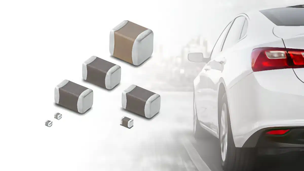
Murata has started mass production of seven new AEC‑Q200 automotive MLCCs that claim world‑leading capacitance for their rated voltage and case size.

These Murata MLCC capacitors target space‑constrained ADAS, autonomous driving ECUs and in‑vehicle power lines, where higher capacitance and miniaturization are increasingly critical for stable operation.

RelatedPosts

Murata Introduces Crystal and NTC Set for Automotive UWB Timing

Murata New MLCC Bulk Case Packaging Cuts Packaging Material by 99%

Murata to Decouple China Rare Earth Supply in 3 Years

Key features and benefits

Murata’s new lineup consists of five low‑voltage GCM series MLCCs rated at 2.5–4 Vdc for IC peripheral circuits, and two 25 Vdc types for automotive power line decoupling. The common theme is maximum capacitance in the smallest possible case, directly addressing PCB area limitations in modern vehicles.

Key characteristics:

  • AEC‑Q200 qualified for automotive use.
  • X7T/X7S‑class high‑capacitance dielectrics (per GCM D7/C7 coding) for broad operating temperature coverage and stable performance versus voltage and frequency, according to the manufacturer’s datasheet.
  • Capacitance values up to 220 µF at 4 Vdc in 1210 size and up to 100 µF at 2.5–4 Vdc in 1206 size.
  • Industry‑leading capacitance density in tiny 0201 and 0402 case sizes for local decoupling and power integrity.

Practical benefits for design engineers:

  • Space savings on dense ADAS/AD PCBs by replacing larger case sizes or parallel MLCC arrays.
  • Improved supply voltage stability on high‑speed SoCs and sensors through higher local bulk capacitance.
  • Potential reduction of component count, which simplifies placement, improves assembly yield and can reduce overall BOM cost.
  • Lower environmental impact by reducing PCB material usage and power consumption during manufacturing.

Typical applications

The new MLCCs are tailored for modern in‑vehicle electronics where both logic rails and power lines are under stress from dynamic loads.

Typical application areas:

  • ADAS and autonomous driving ECUs: local decoupling around SoCs, CPUs, GPUs and high‑speed memory.
  • Camera and radar modules: stabilization of low‑voltage rails powering image sensors, radar front ends and serializers.
  • In‑vehicle infotainment and connected gateways: bulk capacitance near communication processors and high‑speed interfaces.
  • Automotive power lines (25 Vdc parts): filtering and decoupling on 12 V or 24 V derived rails inside ECUs.
  • Electric powertrain and body electronics: space‑constrained control boards requiring high capacitance density on low‑voltage domains.

In many of these positions, higher capacitance in a smaller footprint allows engineers to shorten supply paths, improve transient response and free PCB area for additional functions.

Technical highlights

Murata highlights several “world’s largest capacitance” points for given voltage and size classes, based on its own research as of April 7, 2026. The lineup covers both ultra‑small 0201 chips and larger 1206/1210 sizes used as local bulk capacitors.

Low‑voltage MLCCs for IC peripheral circuits (2.5–4 Vdc)

These parts target core and I/O rails around digital ICs in ADAS and autonomous driving systems.

Murata part numberRated voltage (Vdc)Capacitance (µF)Case size (inch)Approx. size (mm)Target useHighlight
GCM035D70E225ME022.52.202010.6 × 0.3Local decoupling at IC pinsWorld’s largest capacitance for this V/size
GCM31CD70E107ME362.510012063.2 × 1.6Bulk decoupling on low‑voltage railsWorld’s largest capacitance for this V/size
GCM035D70G225MEC242.202010.6 × 0.3High‑density decoupling in tight spacesWorld’s largest capacitance for this V/size
GCM31CD70G107ME36410012063.2 × 1.6Bulk decoupling around digital ICsWorld’s largest capacitance for this V/size
GCM32ED70G227MEC4422012103.2 × 2.5Local bulk capacitance for ADAS/autonomous ECUsWorld’s largest capacitance for this V/size

The D7/C7 dielectric codes indicate high‑capacitance temperature‑stable materials suitable for automotive temperature ranges; exact limits and capacitance change versus temperature and DC bias should be taken from the manufacturer datasheet.

Medium‑voltage MLCCs for power lines (25 Vdc)

Two additional parts address in‑vehicle power line filtering and decoupling.

Murata part numberRated voltage (Vdc)Capacitance (µF)Case size (inch)Approx. size (mm)Target useHighlight
GCM155D71E105KE3625104021.0 × 0.5High‑frequency decoupling on 12/24 V railsWorld’s largest capacitance for this V/size
GCM31CC71E226ME36252212063.2 × 1.6Bulk decoupling on in‑vehicle power linesWorld’s largest capacitance for this V/size

For power line applications, designers should verify ripple current, temperature rise, DC‑bias derating and AC impedance behavior versus frequency in the Murata impedance plots.

Murata provides a consolidated product information page listing these part numbers for detailed parametric search, datasheet access and stocking information. Exact tolerances, temperature characteristics, derating curves and reliability data should be taken from the respective datasheets.

Design‑in notes for engineers

For ADAS and autonomous driving ECUs, power integrity is becoming one of the key bottlenecks as SoCs and sensors scale in complexity. These new MLCCs allow engineers to place more effective capacitance closer to critical IC pins without expanding board area.

Practical design‑in considerations:

  • DC bias derating: high‑capacitance MLCCs in small sizes can show significant capacitance reduction under rated DC voltage. Always design to the effective capacitance under operating conditions rather than the nominal value and consult Murata’s C‑V characteristics.
  • Case size versus mechanical stress: 0201 and 0402 parts are attractive for density but demand precise assembly and careful PCB layout to avoid cracking due to bending. For mechanically stressed boards (large modules, connectors at edges), 1206/1210 types may offer better robustness when combined with suitable pad design.
  • ESR/ESL and frequency behavior: one 100 µF MLCC does not behave identically to an array of smaller capacitors. Check impedance versus frequency; an optimized mix of a high‑value bulk capacitor and a few smaller values in parallel sometimes offers better broadband decoupling.
  • Thermal environment: in engine bay or powertrain locations, capacitor temperature can approach the upper specification limit. Combine these MLCCs with realistic thermal simulations and derating policies, and verify self‑heating under ripple conditions.
  • Qualification and sourcing: all parts are AEC‑Q200 qualified according to Murata, but OEM‑specific validation procedures still apply. Early coordination with purchasing on availability, lifecycle and second‑source strategy is recommended.

For power line decoupling at 25 Vdc, pay particular attention to surge and transient conditions versus rated voltage. In some cases, designers may combine these MLCCs with other technologies such as aluminum electrolytic or polymer capacitors to handle longer‑duration load steps or to meet specific EMC standards.

Source

This article is based on information published by Murata Manufacturing Co., Ltd. in its April 8, 2026 product and event news release on new automotive MLCCs, supplemented by the official product information page and associated datasheet resources.

References

  1. Murata press release: Murata begins mass production of seven automotive MLCCs with world‑leading capacitance for their rated voltage and size
  2. Murata product information: MLCCs GCM035D70E225ME02, GCM31CD70E107ME36, GCM035D70G225MEC2, GCM31CD70G107ME36, GCM32ED70G227MEC4, GCM155D71E105KE36, GCM31CC71E226ME36

Related

Recent Posts

Nichicon Extends Rechargeable Batteries Temperature to Rival Supercapacitors

19.5.2026
16

Two‑capacitor paradox explained for engineers

18.5.2026
33

ESA SPCD 26 Registration Open

15.5.2026
23

Capacitances of Nonlinear MLCCs: What Datasheets Don’t Tell You

14.5.2026
81

Stackpole Releases Automotive Wide‑Termination Resistors

14.5.2026
26

How a Digital Structural Twin Can Predict Tantalum Capacitor Reliability

14.5.2026
57

SCHURTER Buys Biaodi to Boost High-Voltage Protection Portfolio

14.5.2026
52

Researchers Propose Next‑Gen Compact Memory Using Ultra-thin Ferroelectric Capacitors

11.5.2026
51

Nichicon ADN Automotive Hybrid Aluminum Capacitors Now Available in EMEA

11.5.2026
44

Upcoming Events

May 19
16:00 - 17:00 CEST

Designing Qi2 Wireless Power Systems: Practical Development and EMC Optimization

Jun 2
16:00 - 17:00 CEST

Calculation, Simulation and Measurement of 800V EMC Filters

Jun 16
16:00 - 17:00 CEST

EMC with EMC – EMC‑compliant design with electromechanical connectors

View Calendar

Popular Posts

  • Buck Converter Design and Calculation

    0 shares
    Share 0 Tweet 0
  • Boost Converter Design and Calculation

    0 shares
    Share 0 Tweet 0
  • Flyback Converter Design and Calculation

    0 shares
    Share 0 Tweet 0
  • LLC Resonant Converter Design and Calculation

    0 shares
    Share 0 Tweet 0
  • MLCC and Ceramic Capacitors

    0 shares
    Share 0 Tweet 0
  • Capacitor Charging and Discharging

    0 shares
    Share 0 Tweet 0
  • What Electronics Engineer Needs to Know About Passive Low Pass Filters

    0 shares
    Share 0 Tweet 0
  • Dual Active Bridge (DAB) Topology

    0 shares
    Share 0 Tweet 0
  • Ripple Current and its Effects on the Performance of Capacitors

    3 shares
    Share 3 Tweet 0
  • MLCC Case Sizes Standards Explained

    0 shares
    Share 0 Tweet 0

Newsletter Subscription


Passive Components Blog

© EPCI - Leading Passive Components Educational and Information Site

  • Home
  • Privacy Policy
  • EPCI Membership & Advertisement
  • About

No Result
View All Result
  • Home
  • Knowledge Blog
  • PCNS

© EPCI - Leading Passive Components Educational and Information Site

This website uses cookies. By continuing to use this website you are giving consent to cookies being used. Visit our Privacy and Cookie Policy.
Go to mobile version