Passive Components Blog
No Result
View All Result
  • Home
  • NewsFilter
    • All
    • Aerospace & Defence
    • Antenna
    • Applications
    • Automotive
    • Capacitors
    • Circuit Protection Devices
    • electro-mechanical news
    • Filters
    • Fuses
    • Inductors
    • Industrial
    • Integrated Passives
    • inter-connect news
    • Market & Supply Chain
    • Market Insights
    • Medical
    • Modelling and Simulation
    • New Materials & Supply
    • New Technologies
    • Non-linear Passives
    • Oscillators
    • Passive Sensors News
    • Resistors
    • RF & Microwave
    • Telecommunication
    • Weekly Digest

    Miniaturization of Tantalum Capacitors: Structural Limit Under Constant Rating

    Heatsink Design and Thermal Interface Materials for Reliable Electronics

    Murata New MLCC Bulk Case Packaging Cuts Packaging Material by 99%

    Wk 17 Electronics Supply Chain Digest

    Exxelia Introduces SMD High‑Voltage Mica Capacitors

    Modelithics Releases COMPLETE v26.1 for Keysight ADS

    April 2026 Interconnect, Passives and Electromechanical Components Market Insights

    SPICE Simulation of Non-Linear Resistors: Vishay’s Thermistor and PPTC Modelling Ecosystem

    KYOCERA AVX Introduces Traction‑Grade DC Link Film Capacitors

    Trending Tags

    • Ripple Current
    • RF
    • Leakage Current
    • Tantalum vs Ceramic
    • Snubber
    • Low ESR
    • Feedthrough
    • Derating
    • Dielectric Constant
    • New Products
    • Market Reports
  • VideoFilter
    • All
    • Antenna videos
    • Capacitor videos
    • Circuit Protection Video
    • Filter videos
    • Fuse videos
    • Inductor videos
    • Inter-Connect Video
    • Non-linear passives videos
    • Oscillator videos
    • Passive sensors videos
    • Resistor videos

    Why Power Inductors Use a Ferrite Core With an Air Gap

    Transformer-Based Power-Line Harvester Magnetic Design

    Thermal Modeling of Magnetics

    Standard vs Planar LLC transformers Comparison for Battery Chargers

    How Modern Tools Model Magnetic Components for Power Electronics

    Advanced Loss Modeling for Planar Magnetics in the Frenetic Planar Tool

    2026 Power Magnetics Design Trends: Flyback, DAB and Planar

    Enabling Software‑Defined Vehicle Architectures: Automotive Ethernet and Zonal Smart Power

    Calculating Resistance Value of a Flyback RC Snubber 

    Trending Tags

    • Capacitors explained
    • Inductors explained
    • Resistors explained
    • Filters explained
    • Application Video Guidelines
    • EMC
    • New Products
    • Ripple Current
    • Simulation
    • Tantalum vs Ceramic
  • Knowledge Blog
  • DossiersNew
  • Suppliers
    • Who is Who
  • PCNS
    • PCNS 2025
    • PCNS 2023
    • PCNS 2021
    • PCNS 2019
    • PCNS 2017
  • Events
No Result
View All Result
Passive Components Blog
No Result
View All Result

SCHURTER Releases Compact SMT DIP Switches

7.4.2026
Reading Time: 7 mins read
A A

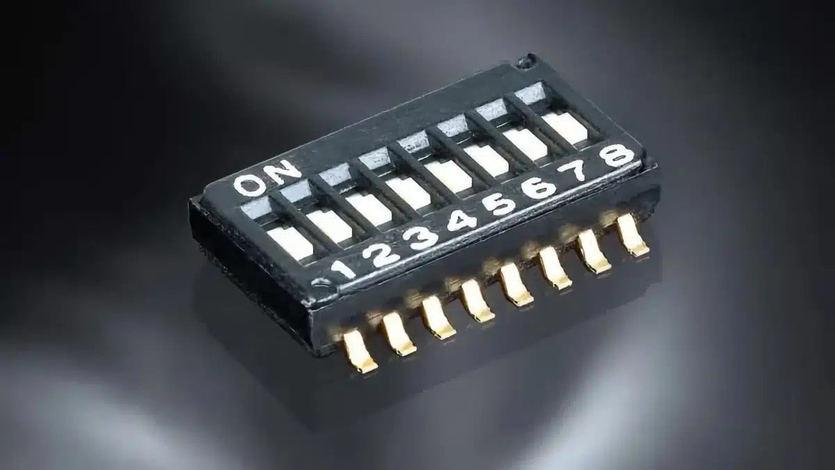
SCHURTER introduces DTCD and DTCJ series ultra‑miniature 1.27 mm pitch SMT DIP switches designed for high‑density electronic assemblies where classic 2.54 mm packages are difficult to fit.

They combine a very low profile with automated SMT compatibility, making them suitable for compact industrial, communication, and embedded systems that still require hardware configuration.

RelatedPosts

SCHURTER Introduces 2410 SMD Fuse for Robust AC/DC Protection

Schurter Releases EKO HV Fuses up to 1000 VDC, 1100 A

SCHURTER Releases Coin Cell Supercapacitors for Backup Power

Compared to conventional DIP switches, these parts can reduce the required PCB area by up to 46% while maintaining typical logic‑level voltage and current ratings. This allows engineers to keep manual configuration points on the board without sacrificing valuable layout area for other functions.

Key features and benefits

The SCHURTER DTCD and DTCJ series address the typical constraints of modern compact PCBs: limited board space, strict height limits, and full SMT assembly flows.

Key construction features include:

  • 1.27 mm switch pitch for high packing density on the PCB.
  • Ultra‑low profile height of approximately 2.2 mm, suitable for stacked boards and enclosures with tight z‑axis clearance.
  • Available as:
    • DTCD: Gullwing terminal version for standard SMT pads and easy visual inspection.
    • DTCJ: J‑bend terminal version for compact footprints and robust solder joints.
  • Designed for automated SMT assembly (pick‑and‑place, reflow), avoiding manual through‑hole insertion.

From an application perspective, the main benefits are:

  • Significant PCB space savings (up to roughly 46% versus 2.54 mm pitch DIP switches), allowing more functions or wider clearance around critical traces.
  • No additional assembly process step; the switches go through the same SMT flow as other components.
  • Hardware configuration remains easily accessible to technicians and field engineers, with clearly defined on/off states.
  • Mechanical endurance of up to about 1000 actuations, sufficient for typical configuration and service operations over product lifetime.

For purchasing and logistics, using a single ultra‑miniature DIP switch platform across multiple designs can simplify BOMs by standardizing on one 1.27 mm family with two terminal variants.

Typical applications

The DTCD and DTCJ series are intended as address and configuration switches in a wide range of equipment where small form factor and SMT assembly are mandatory.

Typical examples include:

  • Industrial control and automation:
    • Node addressing and mode selection in I/O modules, PLC expansion cards, and compact controllers.
    • Configuration of fieldbus or industrial Ethernet interface modules.
  • Communication and networking:
    • Address setting for RS485/Modbus, CAN nodes, or proprietary serial links.
    • Configuration of interface cards or backplane‑connected modules.
  • Computing and embedded systems:
    • BIOS/CMOS configuration or recovery settings on server and storage boards.
    • Boot‑mode or feature selection in embedded controllers and SBCs.
  • Medical and consumer devices:
    • Service modes or regional configuration in medical instruments.
    • Mode or feature selection in high‑end consumer or prosumer appliances.

In practice, these switches are typically used on low‑speed digital lines like address, chip‑select, enable, or mode pins, where a stable manual logic level is required without software access.

Technical highlights

From a technical standpoint, DTCD and DTCJ provide a familiar electrical behavior in a much smaller SMT package:

  • Pitch: 1.27 mm between switch positions.
  • Height: low profile around 2.2 mm.
  • Contact characteristics:
    • Initial contact resistance typically ≤ 100 mΩ.
  • Electrical ratings:
    • Suitable for logic‑level signals, with maximum current and voltage according to manufacturer datasheet (for example, up to around 100 mA at 50 V).
  • Mechanical endurance:
    • Up to approximately 1000 operating cycles.
  • Temperature range:
    • Operation from about −40 °C to +85 °C.

The low contact resistance and defined rating are important for avoiding voltage drops and unstable logic levels on configuration pins, especially when multiple signals share reference lines or pull‑up networks. The specified temperature range covers most industrial and commercial use cases, including equipment deployed in control cabinets and indoor environments.

Gullwing versus J‑bend terminals allow layout engineers to optimize solder pad design, inspection strategy, and mechanical robustness according to their assembly process and reliability targets.

Design‑in notes for engineers

When designing in the DTCD or DTCJ 1.27 mm DIP switches, a few practical aspects help ensure a robust implementation:

  • PCB footprint and land pattern:
    • Use the recommended pad layout from the SCHURTER datasheets for the chosen terminal style.
    • Pay attention to solder mask openings and paste stencil design to avoid tombstoning or insufficient solder fillets on the small terminals.
  • Placement and reflow:
    • Place the switches away from very tall components that could shadow heat flow during reflow.
    • Verify that the chosen reflow profile respects the maximum temperature profile specified by SCHURTER.
  • Mechanical access:
    • Ensure that the actuator area remains accessible after assembly, including any housings, shields, or neighboring connectors.
    • Consider using silk‑screen markings to indicate switch position and on/off orientation for service personnel.
  • Signal integrity and EMC:
    • Route configuration lines as low‑speed signals with appropriate pull‑ups or pull‑downs close to the IC inputs.
    • If configuration lines are long or exposed, adding simple RC filtering or series resistors can improve immunity to ESD and transients.
  • Reliability considerations:
    • Use the DIP switches primarily for configuration that is set at installation or service time, not as frequently toggled user controls.
    • If operation in harsh environments (shock, vibration, strong contamination) is expected, review the application profile against the mechanical and environmental specifications of the datasheet.

By standardizing on this 1.27 mm family, engineers can keep a consistent configuration concept across product generations while freeing valuable PCB area for new functions, extra I/O channels, or improved creepage and clearance around high‑voltage sections.

Source

This article is based on information from SCHURTER’s official press release and product documentation for the DTCD and DTCJ 1.27 mm pitch SMT DIP switches, complemented with general application guidance for board‑level configuration switches.

References

  1. SCHURTER press release – SMT Half Pitch DIP Switches for Space-Critical Applications
  2. SCHURTER DTCD datasheet
  3. SCHURTER DTCJ datasheet

Related

Recent Posts

Exxelia Introduces SMD High‑Voltage Mica Capacitors

28.4.2026
14

April 2026 Interconnect, Passives and Electromechanical Components Market Insights

22.4.2026
59

KYOCERA AVX Introduces Traction‑Grade DC Link Film Capacitors

21.4.2026
41

YAGEO Introduces High‑Current Y2/X1 Film Capacitors for Wide-bandgap Power Systems

17.4.2026
35

Amphenol Explanded Liquid Cooling Connectors for AI, ESS and EV Systems

17.4.2026
21

Hirose Introduced BGA connector for PCIe Gen6 for AI and Edge Computing

17.4.2026
12

Samsung Introduces Ultra-High-Voltage 1500 V MLCCs for xEV Powertrains

16.4.2026
28

TDK Introduces High‑Voltage Common‑Mode Chokes for Compact 1250 V DC Converters

16.4.2026
32

Vishay Extends Power Inductors for DC/DC with 1212 Compact Case

16.4.2026
24

Upcoming Events

Apr 29
10:00 - 11:00 CDT

SEPIC Design Done Right

Apr 30
10:00 - 11:00 CDT

Programming Embedded Systems

May 5
16:00 - 17:00 CEST

Understanding and Selecting Capacitors – Fundamentals, Technologies and Latest Trends

View Calendar

Popular Posts

  • Buck Converter Design and Calculation

    0 shares
    Share 0 Tweet 0
  • Boost Converter Design and Calculation

    0 shares
    Share 0 Tweet 0
  • Flyback Converter Design and Calculation

    0 shares
    Share 0 Tweet 0
  • LLC Resonant Converter Design and Calculation

    0 shares
    Share 0 Tweet 0
  • MLCC and Ceramic Capacitors

    0 shares
    Share 0 Tweet 0
  • Dual Active Bridge (DAB) Topology

    0 shares
    Share 0 Tweet 0
  • What Electronics Engineer Needs to Know About Passive Low Pass Filters

    0 shares
    Share 0 Tweet 0
  • Capacitor Charging and Discharging

    0 shares
    Share 0 Tweet 0
  • MLCC Case Sizes Standards Explained

    0 shares
    Share 0 Tweet 0
  • Ripple Current and its Effects on the Performance of Capacitors

    3 shares
    Share 3 Tweet 0

Newsletter Subscription


Passive Components Blog

© EPCI - Leading Passive Components Educational and Information Site

  • Home
  • Privacy Policy
  • EPCI Membership & Advertisement
  • About

No Result
View All Result
  • Home
  • Knowledge Blog
  • PCNS

© EPCI - Leading Passive Components Educational and Information Site

This website uses cookies. By continuing to use this website you are giving consent to cookies being used. Visit our Privacy and Cookie Policy.
Go to mobile version