Passive Components Blog
No Result
View All Result
  • Home
  • NewsFilter
    • All
    • Aerospace & Defence
    • Antenna
    • Applications
    • Automotive
    • Capacitors
    • Circuit Protection Devices
    • electro-mechanical news
    • Filters
    • Fuses
    • Inductors
    • Industrial
    • Integrated Passives
    • inter-connect news
    • Market & Supply Chain
    • Market Insights
    • Medical
    • Modelling and Simulation
    • New Materials & Supply
    • New Technologies
    • Non-linear Passives
    • Oscillators
    • Passive Sensors News
    • Resistors
    • RF & Microwave
    • Telecommunication
    • Weekly Digest

    3-Phase EMI Filter Design, Simulation, Calculation and Test

    YAGEO Unveils Compact 2.4 GHz SMD Antenna

    KYOCERA AVX Releases Antenna for Iridium Satellite IoT Applications

    Molex Releases Industry-First Quad-Row Board-to-Board Connectors with EMI Shields

    Image credit: Samtec

    How to Match the Right Connector with Protocol Requirements

    Smoltek CNF-MIM Capacitors Pass 1,000h Reliability Test

    Capacitor Lead Times: October 2025

    Paumanok Unveils Aluminum Capacitor Foils World Markets Study 2025-2030

    Coilcraft Introduces Ultra-Low Loss Shielded Power Inductors

    Trending Tags

    • Ripple Current
    • RF
    • Leakage Current
    • Tantalum vs Ceramic
    • Snubber
    • Low ESR
    • Feedthrough
    • Derating
    • Dielectric Constant
    • New Products
    • Market Reports
  • VideoFilter
    • All
    • Antenna videos
    • Capacitor videos
    • Circuit Protection Video
    • Filter videos
    • Fuse videos
    • Inductor videos
    • Inter-Connect Video
    • Non-linear passives videos
    • Oscillator videos
    • Passive sensors videos
    • Resistor videos

    3-Phase EMI Filter Design, Simulation, Calculation and Test

    Transformer Design Optimization for Power Electronics Applications

    Common Mode Chokes Selection for RF Circuits in Next-Generation Communication Systems

    Capacitor Self-balancing in a Flying-Capacitor Buck Converter

    How to Select Ferrite Bead for Filtering in Buck Boost Converter

    Power Inductors Future: Minimal Losses and Compact Designs

    Percolation Phenomenon: Degradation of Molded Power Inductors in DC/DC Converters

    Connector PCB Design Challenges

    Efficient Power Converters: Duty Cycle vs Conduction Losses

    Trending Tags

    • Capacitors explained
    • Inductors explained
    • Resistors explained
    • Filters explained
    • Application Video Guidelines
    • EMC
    • New Products
    • Ripple Current
    • Simulation
    • Tantalum vs Ceramic
  • Knowledge Blog
  • Suppliers
    • Who is Who
  • PCNS
    • PCNS 2025
    • PCNS 2023
    • PCNS 2021
    • PCNS 2019
    • PCNS 2017
  • Events
No Result
View All Result
Passive Components Blog
No Result
View All Result

Microscopic Magnetic Structures Revealed

17.12.2015
Reading Time: 2 mins read
A A

source: ECN article

Wed, 12/16/2015 – 2:32pm by Tohoku University

RelatedPosts

3-Phase EMI Filter Design, Simulation, Calculation and Test

YAGEO Unveils Compact 2.4 GHz SMD Antenna

KYOCERA AVX Releases Antenna for Iridium Satellite IoT Applications

The research group of Professor Hideo Ohno and Associate Professor Shunsuke Fukami of Tohoku University has studied in detail, a slow change of microscopic magnetic structures in metallic wires induced by external driving forces, commonly called “creep” motion. This has allowed them to clarify the physics of how the driving forces, magnetic fields or electric currents, act on the magnetic structure.

Previous studies had shown that while the actions of magnetic fields and currents are the same for metallic materials, they are fundamentally different for semiconductor materials.

The present study reveals that in cases where the sample satisfies a certain condition, the current acts on the magnetic structure in a different manner from the magnetic field case, irrespective of the intricacies of the material.

The development of a high-performance magnetic memory device (where the magnetic structure is manipulated by current) has been intensively pursued recently, and the present findings are expected to facilitate the fundamental understanding to achieve the practical application.

The research group fabricated a wire device consisting of a ferromagnetic metal CoFeB, and investigated the universality class of a magnetic domain wall “creep”. They evaluated the domain wall velocity for various magnitudes of magnetic field or electric current while keeping the device temperature constant, from which they derived the scaling exponent for the universality class.

The results indicate that the scaling exponent does not depend on factors such as temperature and wire width, for both magnetic field and current cases, confirming the universality of the observed feature. Interestingly, unlike the previous study on metallic systems, they found different universality classes between magnetic field and current-driven domain wall creeps in the present metallic sample.

This means that the actions of a magnetic field and current on the domain wall are fundamentally different from each other. The field-driven “creep” was found to belong to a previously known universality class, whereas the current-driven “creep” was found to belong to a different universality class which cannot be explained by the present theories and the scaling exponent was similar to the one observed previously in the magnetic semiconductor.

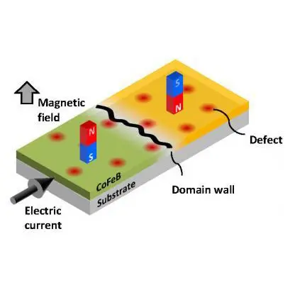
From detailed investigations of the behavior of the domain wall under the application of a current, they found that the current gives rise to an adiabatic spin-transfer torque acting on the domain wall which has a different symmetry to the torque induced by a magnetic field. In other words, it was clarified that, for sample in which stack structure is designed so that the adiabatic spin-transfer torque dominantly affects the domain wall, universal creep characteristics appear irrespective of the nature of material, such as metal or semiconductor, the details of microscopic structure.

The obtained findings shed light on a statistical physics of creep motion of elastic interfaces and development of high-performance magnetic memory devices.

Featured Picture: Schematic of domain wall creep. When a very weak magnetic field or electric current is applied to the magnetic wire with domain wall, the domain wall behaves as an elastic interface and slowly moves, creeps.

Related

Recent Posts

3-Phase EMI Filter Design, Simulation, Calculation and Test

6.11.2025
6

Paumanok Unveils Aluminum Capacitor Foils World Markets Study 2025-2030

6.11.2025
3

Coilcraft Introduces Ultra-Low Loss Shielded Power Inductors

6.11.2025
3

Exxelia Presents Smart Integrated Magnetics Solution at Space Tech Expo 2025 

5.11.2025
13

Murata Expands High Cutoff Frequency Chip Common Mode Chokes

5.11.2025
6

Transformer Design Optimization for Power Electronics Applications

4.11.2025
11

Bourns Releases High Current Metal Alloy-based, Multilayer Power Chip Inductors

31.10.2025
27

Common Mode Chokes Selection for RF Circuits in Next-Generation Communication Systems

30.10.2025
16

Vishay Releases Space-Grade 150 W 28V Planar Transformers

29.10.2025
29

How to Select Ferrite Bead for Filtering in Buck Boost Converter

23.10.2025
53

Upcoming Events

Nov 11
17:00 - 18:00 CET

Industrial Applications Demand More from Interconnects in Next-Gen Designs

Nov 12
11:00 - 12:00 CET

PCB Design: Impedance is for everyone!

Nov 12
November 12 @ 12:00 - November 13 @ 14:15 EST

Microelectronic Packaging Failure Modes and Analysis

View Calendar

Popular Posts

  • Buck Converter Design and Calculation

    0 shares
    Share 0 Tweet 0
  • Boost Converter Design and Calculation

    0 shares
    Share 0 Tweet 0
  • LLC Resonant Converter Design and Calculation

    0 shares
    Share 0 Tweet 0
  • Flyback Converter Design and Calculation

    0 shares
    Share 0 Tweet 0
  • Ripple Current and its Effects on the Performance of Capacitors

    3 shares
    Share 3 Tweet 0
  • MLCC and Ceramic Capacitors

    0 shares
    Share 0 Tweet 0
  • Dual Active Bridge (DAB) Topology

    0 shares
    Share 0 Tweet 0
  • What is a Dielectric Constant and DF of Plastic Materials?

    4 shares
    Share 4 Tweet 0
  • SEPIC Converter Design and Calculation

    0 shares
    Share 0 Tweet 0
  • Flying Capacitors

    0 shares
    Share 0 Tweet 0

Newsletter Subscription


Passive Components Blog

© EPCI - Leading Passive Components Educational and Information Site

  • Home
  • Privacy Policy
  • EPCI Membership & Advertisement
  • About

No Result
View All Result
  • Home
  • Knowledge Blog
  • PCNS

© EPCI - Leading Passive Components Educational and Information Site

This website uses cookies. By continuing to use this website you are giving consent to cookies being used. Visit our Privacy and Cookie Policy.
Go to mobile version