Passive Components Blog
No Result
View All Result
  • Home
  • NewsFilter
    • All
    • Aerospace & Defence
    • Antenna
    • Applications
    • Automotive
    • Capacitors
    • Circuit Protection Devices
    • electro-mechanical news
    • Filters
    • Fuses
    • Inductors
    • Industrial
    • Integrated Passives
    • inter-connect news
    • Market & Supply Chain
    • Market Insights
    • Medical
    • Modelling and Simulation
    • New Materials & Supply
    • New Technologies
    • Non-linear Passives
    • Oscillators
    • Passive Sensors News
    • Resistors
    • RF & Microwave
    • Telecommunication
    • Weekly Digest

    Supercapacitors Emerge as a Promising Solution to AI-Induced Power Energy Spikes

    Wk 18 Electronics Supply Chain Digest

    YAGEO Releases High Current SMD Common Mode Choke With Shape Core Construction

    Murata and NIMS Built New Database of Dielectric Material Properties

    Tariffs Crush Sales Sentiment in April 2025 ECST Results

    High-Density PCB Assemblies For Space Applications

    Solid State Polymer Multilayer Capacitors For High Temperature Application

    Graphene-Based BOSC Bank Of Supercapacitor Cells

    W-band Self-Biased Circulators for Next Gen VHTS Satellites

    Trending Tags

    • Ripple Current
    • RF
    • Leakage Current
    • Tantalum vs Ceramic
    • Snubber
    • Low ESR
    • Feedthrough
    • Derating
    • Dielectric Constant
    • New Products
    • Market Reports
  • VideoFilter
    • All
    • Antenna videos
    • Capacitor videos
    • Circuit Protection Video
    • Filter videos
    • Fuse videos
    • Inductor videos
    • Inter-Connect Video
    • Non-linear passives videos
    • Oscillator videos
    • Passive sensors videos
    • Resistor videos

    Coupled Inductors in Multiphase Boost Converters

    VPG Demonstrates Precision Resistor in Cryogenic Conditions

    Comparison Testing of Chip Resistor Technologies Under High Vibration

    EMC Challenges for High Speed Signal Immunity and Low EMI

    MOSFET Gate Drive Resistors Power Losses

    Modified Magnetic Reluctance Equivalent Circuit and its Implications

    Improving Common Mode Noise Reduction while Decreasing BOM

    Die and Wire PCB Bonding Explained

    Rogowski Coil Current Sensor Explained

    Trending Tags

    • Capacitors explained
    • Inductors explained
    • Resistors explained
    • Filters explained
    • Application Video Guidelines
    • EMC
    • New Products
    • Ripple Current
    • Simulation
    • Tantalum vs Ceramic
  • Knowledge Blog
  • Suppliers
    • Who is Who
  • Events
No Result
View All Result
Passive Components Blog
No Result
View All Result

Noble and Non-Noble Metal Finishes

4.3.2025
Reading Time: 5 mins read
A A

Tin is the dominant non-noble contact finish due to its widespread use in connectors for commercial and industrial applications. Connectors using noble metal finishes, usually gold, can be used in all applications and environments.

Noble Metal Finishes

Connectors using noble metal finishes, usually gold, can be used in all applications and environments. Because they are more expensive than connectors of similar designs using non-noble finishes, due to the cost of gold plating, they are not generally used in commercial applications. They are, however, specified in most computer and telecom applications due to their performance advantages.

RelatedPosts

Polymer Materials and Processing

What is RF Connector

Connector Materials and Processes

A noble metal contact finish is a system consisting of:
• a noble metal surface, usually gold
• a nickel underplate
• the contact spring base metal (copper alloy)

All three elements influence both the electrical and mechanical characteristics of the contact interface.

Electrically the noble metal surface allows for the formation of the metal-to-metal a-spots that create the electrical contact interface; the nickel underplate provides benefits that protect the nobility of the contact interface due to external corrosion mechanisms; and the constriction resistance takes place in the contact spring material.

Mechanically it is the contact surface that will experience the wear process directly; the hardness of the nickel underplate improves the wear resistance of the system; and the hardness of the base metal contact spring influences the overall amount of deformation that occurs. This effect of the contact spring on deformation is due to the low thickness of the gold and nickel platings, of the order of microns, so that the stresses applied to the contact interface penetrate into the contact spring.

Fig. 2.1: Noble metal contact finish

Figure 2.1 schematically illustrates a cross section of a noble metal finish. The noble metal surface plating is usually gold. In computer/telecom applications the gold is typically electroplated to thicknesses of the order of 0.4 to 0.8 µm (15 to 30 microinches). The gold plating used in connectors is typically a “hard” gold. Hard golds are lightly alloyed, 0.1 percent, with cobalt, nickel or iron, with cobalt being the most common. There is an alternative noble metal finish using palladium alloys. The most common palladium alloy is palladium (80)-nickel (20) with palladium (80)-cobalt (20) also used. In this case the bulk of the plating thickness is palladium alloy, but the surface plating may be a gold flash. A flash is a thin plating of the order of a tenth of a micron (4 microinches) in thickness.

The nickel underplate is typically electroplated to thicknesses of 1.25 to 2.5 µm (50 to 100 microinches). Recall from Chapter I/1.2.3 Contact Finishes that the nickel underplate provides several benefits with respect to corrosion and wear which will be discussed in Chapter II/2.1.2 Contact Finish Degradation Mechanisms.

Whisker:
Whiskers are single crystal fibres (when pure Tin plating is used) which can cause electrical failures. Lead was a good way to prevent them as there was no Tin whisker problem while Sn-Pb was the major plating used in the connector industry. Whisker density, length and shape are quite different and unpredictable and can lead to transient or permanent shorts in electric and electronic circuits. Either directly on the component where they have grown or (if they break loose) somewhere else in the circuit.

Fig. 2.2: Whisker effect on a pin header (drawing)

In the early 2000 years whiskers caused losses of over US$ 1 Billion, mostly in military, satellite and avionic applications, therefore Sn-Pb platings remain active in these fields which are not concerned by the lead free considerations.

Fig. 2.3: Factors that influence the appearance of tin whiskers

The number of factors and their interactions are so complex that the whisker growth mechanism still hasn’t been totally understood. As it’s not the main purpose of this book to study in details the whisker formation principle, we will only state that it’s mostly connector with small pitches, typically 0.5 mm or lower which are potentially subject to this problem.

In order to prevent Tin whisker creation, the most simple and efficient ways known are to:
• Use another plating than pure tin: like gold (full or selective gold …)
• Use Matt tin instead of bright Tin
• Use Ni under plating below the Tin

Non-Noble Metal Finishes

Tin is the dominant non-noble contact finish due to its widespread use in connectors for commercial and industrial applications. Tin finishes are generally electroplated, though reflowed tin coatings are also used. The thickness of electroplated tin is generally in the range of 2.5 to 5.0 µm (100 to 200 microinches) with reflowed coatings being somewhat thicker.

Fig. 2.4: Tin contact finish

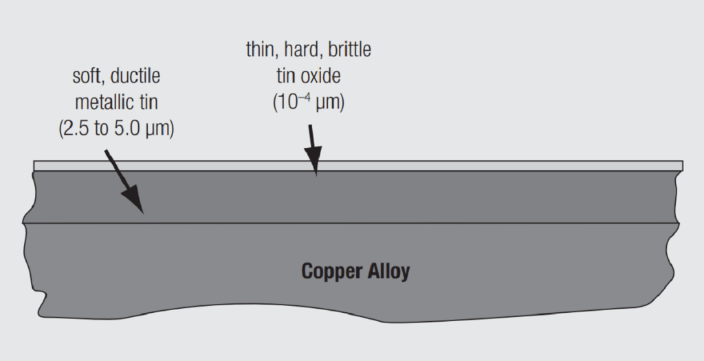
Tin provides corrosion protection to the contact spring due to the self limiting tin oxide film on the tin surface. As indicated in Figure 2.4, the oxide layer is very thin, hard and brittle and is readily displaced on mating of the connector resulting in tin-to-tin metallic contact areas. The major limitation to the use of tin as a general purpose connector contact finish is the fact that a tin-to-tin contact interface is susceptible to reoxidation if the interface experiences small scale movements due to mechanical or thermal stresses in the connector application environment. This degradation mechanism is called fretting corrosion.

Nickel and silver are also used in connector applications. Nickel has an even thinner oxide layer on its surface than tin. Nickel is most commonly used in battery contacts and also in high temperature applications. Silver surface films are primarily sulfides, tarnish films, which are also readily displaced on connector mating. Silver is used primarily in high current contacts due to the high electrical conductivity of silver and a better resistance to arcing damage compared to gold or tin contacts.

Related

Source: Wurth elektronik

Recent Posts

Non-Magnetic Interconnects

23.4.2025
12

10 Tips for Ensuring Reliability of Discrete Wire Assemblies

20.2.2025
49

Polymer Materials and Processing

31.1.2025
32

Basic PCB Technology Overview

17.12.2024
15

What is RF Connector

17.12.2024
7

Creepage and Clearance of Connector

16.10.2023
9

Microwave Multi Line Connectors Mounting and Handling Precautions

17.12.2024
2

BASIC PCB Design Rules – Layout

17.12.2024
21

MEMR RF Relay for Space Compact Redundancy Ring

17.12.2024
2

Connector Temperature Rise and Derating

13.1.2023
11

Upcoming Events

May 14
11:00 - 12:00 CEST

Reliable RIGID.flex PCBs for Critical Applications – Made in Europe

May 28
16:00 - 17:00 CEST

Power Over Data Line

View Calendar

Popular Posts

  • Buck Converter Design and Calculation

    0 shares
    Share 0 Tweet 0
  • Flyback Converter Design and Calculation

    0 shares
    Share 0 Tweet 0
  • What is a Dielectric Constant and DF of Plastic Materials?

    4 shares
    Share 4 Tweet 0
  • Boost Converter Design and Calculation

    0 shares
    Share 0 Tweet 0
  • LLC Resonant Converter Design and Calculation

    0 shares
    Share 0 Tweet 0
  • Coefficient of Linear Thermal Expansion on Polymers Explained

    0 shares
    Share 0 Tweet 0
  • SEPIC Converter Design and Calculation

    0 shares
    Share 0 Tweet 0
  • Ripple Current and its Effects on the Performance of Capacitors

    3 shares
    Share 3 Tweet 0
  • What Electronics Engineer Needs to Know About Passive Low Pass Filters

    0 shares
    Share 0 Tweet 0
  • Dual Active Bridge (DAB) Topology Explained

    0 shares
    Share 0 Tweet 0

Newsletter Subscription


Passive Components Blog

© EPCI - Leading Passive Components Educational and Information Site

  • Home
  • Privacy Policy
  • EPCI Membership & Advertisement
  • About

No Result
View All Result
  • Home
  • Knowledge Blog
  • Premium Suppliers

© EPCI - Leading Passive Components Educational and Information Site

This website uses cookies. By continuing to use this website you are giving consent to cookies being used. Visit our Privacy and Cookie Policy.
Go to mobile version