


This article by Dr. V. Azbel, an Independent consultant on tantalum capacitors, discusses modeling of tantalum capacitor anode structure to optimize tantalum capacitor performance via understanding the interface zone.
Introduction
Tantalum capacitors are widely used in electronics due to their high specific capacitance, reliability, and durability. However, one key challenge remains DCL leakage currents, which adversely affect device performance.
In the design of the tantalum capacitors (TC), the anode is primarily responsible for the DCL.
The stability of the DCL anode is ensured by the resistance of its structure to the aging process under the influence of external factors. The anode structure consists of porous sintered tantalum, an amorphous film of tantalum oxide (Ta₂O₅), and an interface zone between them, which is an integral product of tantalum oxidation.
Currently, the understanding of the structural characteristics of the interface zone and its impact on DCL is limited. Manufacturers often rely on empirical methods, such as wet testing, when selecting powder characteristics and formation conditions.
This paper proposes a structural model of the anode that explains the nature of residual stresses and suggests approaches to optimizing the manufacturing process of anodes to minimize leakage currents.
Problem and Existing Approach
Manufacturers of tantalum powders provide recommendations for their CV/g to ensure desired capacitance and formation voltage characteristics. However, the selection of formation parameters is largely based on empirical experience.
The interface zone between metallic Ta and the amorphous Ta₂O₅ film (ATO) significantly influences the magnitude and stability of the anode’s leakage current. The precise structure of this zone, its chemical and physical properties, and the mechanisms of its formation are not yet well understood. This lack of understanding hinders the scientifically grounded optimization of formation processes.
Proposed Structural Model of the Anode
The anode can be conceptualized as a structure composed of two phases (Ta and amorphous Ta₂O₅) and three structural states:
- Monocrystalline or microcrystalline Ta.
- Amorphous Ta₂O₅.
- The interface zone between them
The Tantalum Neck as a Component of a Porous Sintered Pellet
The tantalum neck is a narrow bridge connecting two sintered primary powder particles. Due to its small size, specific sintering process, and high chemical purity of tantalum, the neck’s structure is coarse-grained or nearly monocrystalline. This structure exhibits high plasticity and low yield strength.
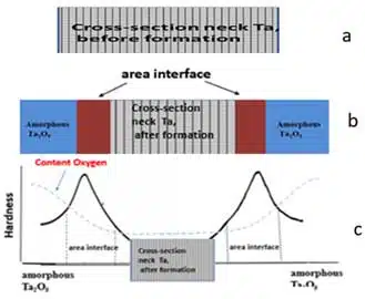
The Interface Zone
After formation, the active part of the tantalum neck (center) is surrounded by an amorphous Ta₂O₅ layer and the interface zone between the tantalum neck and Ta₂O₅ (see Fig. 1b). The interface zone is not a distinct phase, a modified region of the tantalum neck, forming a volumetric layer with a nanograined structure that separates the tantalum neck from the amorphous Ta₂O₅. This zone is formed as a byproduct of electrolysis and cannot be directly controlled, unlike sintering or formation processes. The volume of the interface zone is negligible compared to the volumes of the tantalum neck and the amorphous Ta₂O₅.
The nanograined structure, the interface zone, exhibits high hardness (see Fig. 1c), high yield strength, and low plasticity. Despite the high yield strength of this zone, its contribution to the overall yield strength of the anode is minimal due to its small volume relative to the anode.
The Amorphous Ta₂O₅ Film
The amorphous Ta₂O₅ film has a disordered structure, precluding grain formation and resulting in a complete absence of plasticity. It forms during electrochemical oxidation, a process that can also produce other byproducts, such as the nanograined structure in the interface zone. This film is brittle and unable to withstand mechanical loads but plays a critical functional role in the anode structure. It acts as a diffusion barrier and ensures a high degree of electrical insulation. However, its structural features can lead to localized failures or defects under external stresses.
Hardness Distribution and Material Properties
The hardness distribution graph (see Fig. 1c) shows that each structural component of the anode corresponds to a specific hardness level, with peak values observed in the interface zone between distinct phases (black lines, Fig. 1c). The maximum oxygen concentration is localized in the amorphous Ta₂O₅ film (blue line, Fig. 1c). Studies /2/ have demonstrated that the hardness of composite coatings correlates with residual stresses, allowing an assessment of the influence of internal stresses on the material’s mechanical properties.
According to the above, the tantalum neck, interface zone, and amorphous Ta₂O₅ film each possess distinct structural and mechanical properties. While the coarse-grained tantalum neck provides high plasticity, the nano-grained interface zone and amorphous Ta₂O₅ offer high hardness and functional insulation, respectively. Despite their individual limitations, these components collectively enable the anode to function effectively.
Impact of Gradients on Anode Stability: The diagram (see Fig. 1c) illustrates the presence of gradients of hardness and oxygen concentration in the structure of the anode, which is an integral part of the technological process of its production
The presence of a gradient in the material increases the risk of the structure losing its stability under external influence, the occurrence of internal stresses, and the risk of aging.
The intersection of gradients should form a region of minimum energy of the system, in the most critical region, localized in the interface zone
It is reasonable to assume that the anode’s structure remains stable as long as the balance between the opposing gradients in the interface zone is maintained.
This balance is achieved by managing production parameters, such as the porous material’s structural characteristics (neck size, porosity level) and formation parameters.
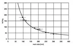
Fig. B (see appendix) shows the dependence of CV/g on neck size, demonstrating how the reduction in neck cross-section due to interface zone growth affects CV/g. This highlights the need to control formation parameters, such as formation voltage (FV), to minimize anode degradation and maintain stability. Disruption of this balance leads to anode material aging.
Key Factors Influencing Gradient Balance:
Relationship Between Neck Size and Formation Voltage
The schematic (see Fig. 2) illustrates the connection between neck size and formation voltage. The growth of ATO during electrochemical processing reduces the neck cross-sectional area (see Fig. 2A).
The formation and growth of ATO result from oxidation, (see Fig. 2B), accompanied by the development of an interface zone. Fig. 2B depicts the oxide film growth model, illustrating the mechanism of interface zone formation between the old and new surfaces.
This process involves the intake of the original tantalum material and the creation of a new oxide structure, altering the neck’s size and morphology. The interaction between the oxide and the interface also plays a critical role in the development of stress gradients, which must be considered when optimizing formation parameters.
Understanding this mechanism is essential for optimizing formation parameters to minimize anode degradation.
A — the relationship between neck dimensions and formation voltage;
B — process of oxide film growth and formation of the interface zone /3/
Mechanism of Interface Zone Formation
The formation of the structure within the interface zone is governed by two primary mechanisms.”
1. Oxidation Mechanism of Ta /4/
The oxidation mechanism is driven by differences in the thermal expansion coefficients of tantalum oxide and tantalum, leading to the generation of compressive stresses.
Studies on stress evolution caused by oxidation in thin tantalum (Ta) films / 4/ have shown that such films oxidize into a crystalline tantalum dioxide (TaO₂) layer, which then transforms into an amorphous tantalum pentoxide (a-Ta₂O₅) layer. The oxidation of Ta to TaO₂ causes a sharp increase in compressive stress, reaching approximately 3.5 GPa (350 kg/mm²). At the same time, the relaxation of compressive stress is associated with the amorphous nature of the a-Ta₂O₅ layer.
2. Local Temperature Increase Due to Exothermic Reaction
The second mechanism involves a local temperature rise resulting from the exothermic oxidation reaction of Ta₂O₅/TaO₂/Ta, with an activation energy of approximately 190.8 kJ/mol.
Thus, the electrochemical process simultaneously induces a sharp increase in compressive stress and heat release due to the exothermic oxidation process. This process can be considered a combination of mechanical effects (localized stresses) and thermal energy, characteristic of mechanochemical and hydrothermal synthesis. These conditions promote the formation of nanostructures with grain sizes of less than 30 nm, characterized by high grain boundary density, which correlates with increased material hardness and residual stresses in the interface zone of a-Ta₂O₅ and Ta.
From the above, it follows that the interface zone between tantalum and its oxide represents a nanocrystalline structure. This zone is the result, of the transformation of part of the crystalline structure of the tantalum neck (see Fig. 2B), the area of which depends on the rate of TaO₂ formation. In this zone, maximum residual stresses are concentrated, making it critical to anode stability.
The schematic below (see Fig. 3) illustrates the effect of formation voltage (FV) for a single neck size on its cross-sectional area, the interface zone, and associated changes in hardness behavior, correlated with residual stresses.
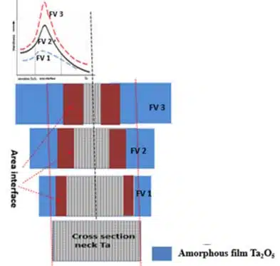
Neck Degeneration and Growth of Internal Stresses
As shown in Fig. 3, increasing the formation voltage (FV) (e.g., from FV1 to FV3) leads to a reduction in the neck cross-sectional area due to the growth of the amorphous Ta₂O₅ film (ATO) and the expansion of the interface zone. The amorphous Ta₂O₅ film formed during formation grows approximately 40% inward and 60% outward (red dashed lines representing neck boundaries in the schematic).
Simultaneously, the increase in FV enlarges the interface zone, further reducing the neck’s active cross-sectional area.
Thus, as FV increases and the interface zone grows, that lead to tantalum neck degeneration occurs. This degeneration causes an increase in hardness and convergence of their peak values, indicating heightened internal stresses in both the neck and the interface zone (see Fig. 3 for hardness growth with increasing FV).
These structural changes in the neck lead to instability in the ATO, increased resistance to current, potential overheating, and elevated equivalent series resistance (ESR), which negatively impact the stability of tantalum capacitors.
Practical Application of the Model: Recommendations for Process Optimization
Based on the proposed anode model and conducted studies, the following recommendations for manufacturers can be formulated:
- Powder Selection
- Use powders with a CV/g within an optimal range to achieve a balance, between porosity and neck.
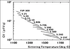
- Fig. A (see appendix) illustrates how sintering temperature changes affect CV/g. These data emphasize the importance of selecting powder with appropriate characteristics to optimize the balance between porosity and size neck.
- Formation Speed
- Adjust formation speed to minimize TaO₂ formation and reduce stresses.
- the proposed virtual anode modeling program / 6 / can analyze parameters affecting formation speed, reducing interface zone stresses and the risk of anode overheating.
- Residual Stress Monitoring
- The proposed method for analyzing the impact of technological parameters on anode structure during production, based on stress-strain curve parameters commonly used in materials science, has been adapted for monitoring manufacturing processes and developing anodes for new tantalum capacitor designs. This approach is detailed in works published on my blog /7/ and LinkedIn.
Conclusion
The proposed model of the tantalum capacitor anode explains the origin of residual stresses and structural degradation. It emphasizes the impact of technological parameters on the formation of hardness gradients and the interface zone. Based on this model, recommendations have been developed to minimize residual stresses, improve the anode structure, and enhance the reliability of the final product. These conclusions are supported by experimental data from the research cycle, ensuring their applicability in real-world production conditions.
For the first time, the mechanism of interface zone formation and its monitoring method has been explained for anode production. This method relies on the parameters of the stress-strain curve rather than direct measurements, offering a novel approach to understanding and controlling this critical aspect of the anode structure.
Appendix
Reference
- J. Musil Hard nanostructured and nanocomposite thin films 2006
- Jae-il Jang Estimation of residual stress by instrumented indentation: A review * Journal of Ceramic Processing Research. Vol. 10, No. 3, pp. 391~4
- Hollauer Christian – 2007 – Modeling of thermal oxidation and stress effects
- Yusung Jin, Thermal oxidation mechanism and stress evolution in Ta thin films, Published online by Cambridge University Press: 31 January 2011
- Correlation of Strength with Hardness and Electrical Conductivity for Aluminum Alloy 7010 Materials Science Forum Vols. 519-521 (2006) pp. 853-858
- Virtual Program for Calculating the Risk of Overheating in the Manufacture of the Anode of a Tantalum Capacitor https://www.linkedin.com/pulse/virtual-program-calculating-risk-overheating-anode-tantalum-azbel/
- V. Azbel blog https://passive-components.eu/tag/azbel/


