Passive Components Blog
No Result
View All Result
  • Home
  • NewsFilter
    • All
    • Aerospace & Defence
    • Antenna
    • Applications
    • Automotive
    • Capacitors
    • Circuit Protection Devices
    • electro-mechanical news
    • Filters
    • Fuses
    • Inductors
    • Industrial
    • Integrated Passives
    • inter-connect news
    • Market & Supply Chain
    • Market Insights
    • Medical
    • Modelling and Simulation
    • New Materials & Supply
    • New Technologies
    • Non-linear Passives
    • Oscillators
    • Passive Sensors News
    • Resistors
    • RF & Microwave
    • Telecommunication
    • Weekly Digest

    Vishay Releases DLA Tantalum Polymer Capacitors for Military and Aerospace

    Vishay Expanded Inductor Portfolio With More Than 2000 Stock Items 

    Paumanok Releases Capacitor Foils Market Report 2025-2030

    Modelithics Welcomes CapV as a Sponsoring MVP

    Wk 40 Electronics Supply Chain Digest

    Benefits of Tantalum Powder Stress–Strain Curve Evaluation vs Conventional Wet Test

    Electrolyte Selection and Performance in Supercapacitors

    Connector PCB Design Challenges

    Researchers Demonstrated High Energy Ceramic Capacitors Stable in Wide Temperature Range

    Trending Tags

    • Ripple Current
    • RF
    • Leakage Current
    • Tantalum vs Ceramic
    • Snubber
    • Low ESR
    • Feedthrough
    • Derating
    • Dielectric Constant
    • New Products
    • Market Reports
  • VideoFilter
    • All
    • Antenna videos
    • Capacitor videos
    • Circuit Protection Video
    • Filter videos
    • Fuse videos
    • Inductor videos
    • Inter-Connect Video
    • Non-linear passives videos
    • Oscillator videos
    • Passive sensors videos
    • Resistor videos

    Connector PCB Design Challenges

    Efficient Power Converters: Duty Cycle vs Conduction Losses

    Ripple Steering in Coupled Inductors: SEPIC Case

    SEPIC Converter with Coupled and Uncoupled Inductors

    Coupled Inductors in SEPIC versus Flyback Converters

    Non-Linear MLCC Class II Capacitor Measurements Challenges

    Percolation Phenomenon and Reliability of Molded Power Inductors in DC/DC converters

    Root Causes and Effects of DC Bias and AC in Ceramic Capacitors

    How to Calculate the Output Capacitor for a Switching Power Supply

    Trending Tags

    • Capacitors explained
    • Inductors explained
    • Resistors explained
    • Filters explained
    • Application Video Guidelines
    • EMC
    • New Products
    • Ripple Current
    • Simulation
    • Tantalum vs Ceramic
  • Knowledge Blog
  • Suppliers
    • Who is Who
  • Events
No Result
View All Result
Passive Components Blog
No Result
View All Result

Planar vs Traditional Transformers in Flyback Converters

8.11.2022
Reading Time: 5 mins read
A A

This blog article written by Pablo Blázquez, Frenetic power electronic engineer, discusses planar transformers for flyback and forward converters with a general overview of the basics and a comparison between planar and traditional transformers.

Flyback and Forward converters are topologies used for low-medium power isolated applications. The Flyback is more suitable for high-voltage outputs, while the forward has the disadvantage of having an extra inductor on the output and is not well suited for high-voltage outputs.

RelatedPosts

Common Mistakes in Flyback Transformer Specs

Accelerating Full Bridge LLC Resonant Converter Design with Frenetic AI

How to design a 60W Flyback Transformer

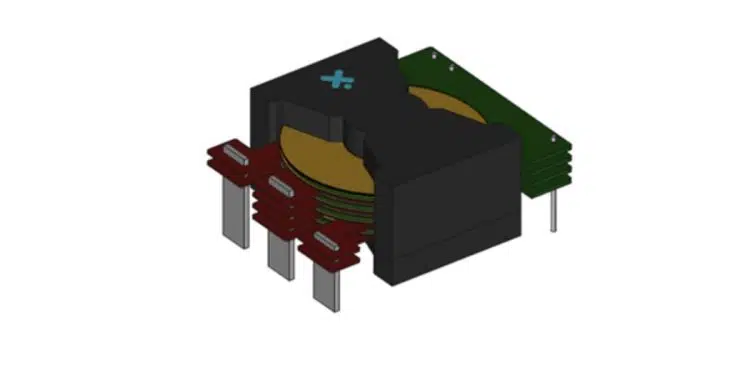
We will analyse how planar transformers can give us more flexibility with these converters when we have space constraints, with a lower leakage inductance, incredibly good repeatability, and great thermal characteristics.

Flyback and Forward considerations

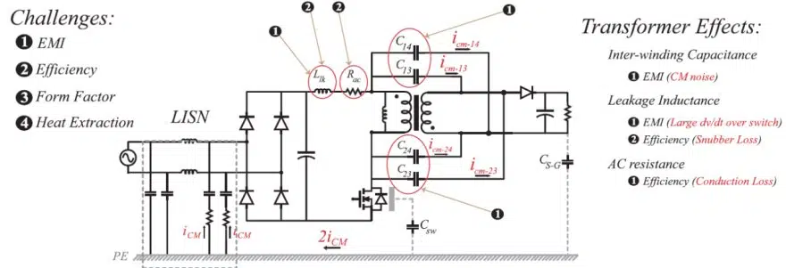
In paper [1] is mentioned that, while designing a Flyback or Forward converter, we will normally face several challenges:

  • ​EMI (Electromagnetic Interferences) losses
  • Efficiency
  • Form factor
  • Heat extraction
Figure 2: Transformer design challenges

Large leakage inductances affect the performance of the transformer creating large voltage spikes on the switch, leading us to use higher-rated voltage switches. Also, this high voltage spike creates common mode noise in the parasitic interwinding capacitance.

The form factor of the transformer, normally the height, will define the size of the converter as well as the places where it can be positioned. For example, a traditional flyback will be difficult to fit in certain low-profile applications, such as headphones or flat TVs.

The higher height is a problem regarding heat transfer, as it generates higher thermal resistance. This happens as the contact surface is more distributed in the planar transformer than in the wound transformer that is more concentrated in one place. 

Planar Transformers or Traditional Transformers?

Traditional Transformers

If we compare planar transformers with traditional ones, we will use less space in the PCB footprint in the wound transformers. So unless power dissipation is a problem, designers will normally use standard transformers.

Winding in traditional transformers is also simple and we know how to do it. The time needed for creating a design and wounding is much lower in traditional transformers.

We will have higher temperatures, as the traditional transformers are limited by the amount of W that the core can dissipate due to the temperature rise. This normally requires forced convection to address this problem, while planar transformers can work with higher W in the core and therefore, we can reduce the losses in the windings. This will give us the possibility of using a heatsink instead of a fan. 

Overall, wound transformers must face all the design considerations in Flyback and Forward converters, but we know how to design and create designs incredibly fast.

Planar Transformers

Planar magnetics are chosen for the high-frequency spectrum because they offer a small number of turns (compared with wound transformers) and extremely low resistance.

Planar transformers can enhance the performance of these converters, as we will be able to have lower height, weight, and leakage inductance. We will have wider surface areas than traditional E, EC, or EP cores. This means that we will be able to have fewer turns, as well as being able to have lower DC resistance. 

Regarding the winding, it is difficult to enter a wire that can handle all this power in such a small space, but the planar transformers’ rigid structure allows us to use PCB windings instead of bobbins. This way we can have lower-profile transformers, as well as a great level of repeatability, as the printed circuit nature of the windings. We will also be able to integrate into the converter´s PCB the windings for having an even more compact design. 

However, there are some drawbacks when designing a planar transformer. We can have problems with safety requirements. Using PCB FR4 can generate problems in the external layer of the windings, top and bottom, and we will need to use traditional isolation methods, like Nomex, to meet those safety requirements.  At least in the internal layers we are covered. Multiple layers can be problematic in the design phase, especially if thick copper plating is required.

Another problem that we will face when designing with Planar transformers is the EMI losses. The flux must travel through the side wall of the core so, the flux on the side will be increased. However, the flux density that we will be having on the central leg will be much lower than in the wound transformer.

Planar transformers are an interesting option for some applications: they have a more complex design than traditional transformers, but can help us in some situations.

Summary

Planar transformer advantages and cons:

Benefits

  • Planar transformers give us extremely low leakage and AC resistance
  • Overall size of the converter is reduced
  • Better heat transfer

Limitation

  • Large interwinding capacitance (Increased CM noise) and causes EMI problems

References

[1] Ali Saket, M. Ordonez, N. Shafiei. (2018). Planar Transformers with Near-Zero Common-Mode Noise for Flyback and Forward Converters (Vol n. º 33) [IEEE]. IEEE Transactions on power electronics.

[2] Achieving Higher Efficiency Using Planar Flyback Transformers for High Voltage AC/DC Converters. Bourns.

[3] “What’s the Difference Between Conventional and Planar Switching Power Transformers? “ Passive Components Blog

Related

Source: Frenetic

Recent Posts

Vishay Expanded Inductor Portfolio With More Than 2000 Stock Items 

8.10.2025
6

Benefits of Tantalum Powder Stress–Strain Curve Evaluation vs Conventional Wet Test

3.10.2025
20

Electrolyte Selection and Performance in Supercapacitors

3.10.2025
16

Connector PCB Design Challenges

3.10.2025
19

Researchers Demonstrated High Energy Ceramic Capacitors Stable in Wide Temperature Range

2.10.2025
24

How to Manage Supercapacitors Leakage Current and Self Discharge 

1.10.2025
39

Experimental Evaluation of Wear Failures in SMD Inductors

1.10.2025
36

Resonant Capacitors in High-Power Resonant Circuits

1.10.2025
37
a Schematic diagram of the BNT-based components constructed based on the entropy-increase strategy. b Digital photograph, cross-sectional SEM image, and EDS mappings of the MLCCs. c Unipolar P-E loops of MLCCs as a function of applied E. d Wrec and η of the MLCCs as a function of applied E. The comparison of (e) Wrec and η, (f) η and UF of the MLCCs with those of other recently reported state-of-the-art MLCCs. source: Nature Communications

Researchers Proposed Enhanced Energy Storage MLCC

1.10.2025
18

Improving SMPS Performance with Thermal Interface Material

30.9.2025
12

Upcoming Events

Oct 14
16:00 - 17:00 CEST

Smart Sensors, Smarter AI: Building Reliable Edge Systems

Oct 17
12:00 - 14:00 EDT

External Visual Inspection per MIL-STD-883 TM 2009

Oct 20
October 20 - October 23

Digital WE Days 2025 – Virtual Conference

Oct 21
October 21 @ 12:00 - October 23 @ 14:15 EDT

Space and Military Standards for Hybrids and RF Microwave Modules

Oct 28
8:00 - 15:00 CET

Power Up Your Design: SN6507 and the Ready-to-Use Development Kit

View Calendar

Popular Posts

  • Buck Converter Design and Calculation

    0 shares
    Share 0 Tweet 0
  • Boost Converter Design and Calculation

    0 shares
    Share 0 Tweet 0
  • Flyback Converter Design and Calculation

    0 shares
    Share 0 Tweet 0
  • LLC Resonant Converter Design and Calculation

    0 shares
    Share 0 Tweet 0
  • SEPIC Converter Design and Calculation

    0 shares
    Share 0 Tweet 0
  • Ripple Current and its Effects on the Performance of Capacitors

    3 shares
    Share 3 Tweet 0
  • Dual Active Bridge (DAB) Topology Explained

    0 shares
    Share 0 Tweet 0
  • What is a Dielectric Constant and DF of Plastic Materials?

    4 shares
    Share 4 Tweet 0
  • Flying Capacitors Explained

    0 shares
    Share 0 Tweet 0
  • MLCC and Ceramic Capacitors

    0 shares
    Share 0 Tweet 0

Newsletter Subscription


Passive Components Blog

© EPCI - Leading Passive Components Educational and Information Site

  • Home
  • Privacy Policy
  • EPCI Membership & Advertisement
  • About

No Result
View All Result
  • Home
  • Knowledge Blog
  • Premium Suppliers

© EPCI - Leading Passive Components Educational and Information Site

This website uses cookies. By continuing to use this website you are giving consent to cookies being used. Visit our Privacy and Cookie Policy.
Go to mobile version