Passive Components Blog
No Result
View All Result
  • Home
  • NewsFilter
    • All
    • Aerospace & Defence
    • Antenna
    • Applications
    • Automotive
    • Capacitors
    • Circuit Protection Devices
    • electro-mechanical news
    • Filters
    • Fuses
    • Inductors
    • Industrial
    • Integrated Passives
    • inter-connect news
    • Market & Supply Chain
    • Market Insights
    • Medical
    • Modelling and Simulation
    • New Materials & Supply
    • New Technologies
    • Non-linear Passives
    • Oscillators
    • Passive Sensors News
    • Resistors
    • RF & Microwave
    • Telecommunication
    • Weekly Digest

    Inductor Resonances and its Impact to EMI

    Developing Low Inductance Film Capacitor using Bode 100 Analyzer

    Highly Reliable Flex Rigid PCBs, Würth Elektronik Webinar

    Würth Elektronik Releases High Performance TLVR Coupled Inductors

    YAGEO Extends Rectangular Aluminum Electrolytic Capacitor Family

    Dr. Tomas Zednicek Vision for Europe 2025 Passive Electronics Market

    Littelfuse Releases Industry-First SMD Fuse with 1500A Interrupting Rating at 277V

    TDK Unveils Industry Highest Rated Current Multilayer Chip Beads

    Vishay Releases Automotive SMD Thick Film Power Resistor for Enhanced Protection Against Short Transient Pulses

    Trending Tags

    • Ripple Current
    • RF
    • Leakage Current
    • Tantalum vs Ceramic
    • Snubber
    • Low ESR
    • Feedthrough
    • Derating
    • Dielectric Constant
    • New Products
    • Market Reports
  • VideoFilter
    • All
    • Antenna videos
    • Capacitor videos
    • Circuit Protection Video
    • Filter videos
    • Fuse videos
    • Inductor videos
    • Inter-Connect Video
    • Non-linear passives videos
    • Oscillator videos
    • Passive sensors videos
    • Resistor videos

    Inductor Resonances and its Impact to EMI

    Highly Reliable Flex Rigid PCBs, Würth Elektronik Webinar

    Causes of Oscillations in Flyback Converters

    How to design a 60W Flyback Transformer

    Modeling and Simulation of Leakage Inductance

    Power Inductor Considerations for AI High Power Computing – Vishay Video

    Coupled Inductors in Multiphase Boost Converters

    VPG Demonstrates Precision Resistor in Cryogenic Conditions

    Comparison Testing of Chip Resistor Technologies Under High Vibration

    Trending Tags

    • Capacitors explained
    • Inductors explained
    • Resistors explained
    • Filters explained
    • Application Video Guidelines
    • EMC
    • New Products
    • Ripple Current
    • Simulation
    • Tantalum vs Ceramic
  • Knowledge Blog
  • Suppliers
    • Who is Who
  • Events
No Result
View All Result
Passive Components Blog
No Result
View All Result

Power Applications

20.9.2021
Reading Time: 4 mins read
A A

Power applications are generally considered “high current/voltage” applications. There are also two aspects to power applications. The first addresses the issue of Joule, I2R, heating in high current contacts which leads to a possibility of definition of “high” as a current sufficient to cause Joule heating to be taken into consideration. The second addresses how current is distributed through the electronic system, by dedicated high current contacts or multiple low current contacts connected in parallel. Current/voltage considerations will be discussed first.

Voltage/Current Considerations
The current and voltage requirements of an application affect the design, materials and performance requirements a connector must meet to be suitable for the application. It must be noted that current and voltage requirement issues are primarily of concern only in power applications because the currents and voltages in typical signal applications will not give rise to the issues to be discussed. The issues to be addressed are different for voltage and current and will be discussed separately.

RelatedPosts

Polymer Materials and Processing

What is RF Connector

Connector Materials and Processes

Voltage Considerations
Voltage considerations involve primarily the design and materials of the connector housing. The issue is the potential for high voltage breakdown of insulators in the connector. The insulators of concern are air, the space between the contacts in the connector housing, and the housing material, the insulation supporting and separating the current carrying contacts in the housing. In both cases voltage breakdown results in unwanted current flow, arcing between contacts in the case of air breakdown, and arcing or leakage currents through or on the surface of the connector housing. Voltage breakdown has both safety and performance aspects. It is important to note that it is the electrical field between the contacts that causes the breakdown. The electric field is given by the quotient of the voltage divided by the separation between the contacts:

The electric field, thus the breakdown voltage, depends on the spacing between the contacts, a distance that has decreased markedly due to connector miniaturization in recent years.

Voltage breakdown concerns are addressed by connector requirements, primarily dictated by safety concerns (arcing), called clearance and creepage distances, illustrated in Figure 2.163. Clearance is the line of sight distance between two power and ground contacts and the clearance requirement is sufficient to ensure that dielectric breakdown of air does not occur. Creepage is the shortest distance along the housing surface between the two points where adjacent power and ground contacts are retained in the housing. The creepage requirement is intended to put limits on the degradation of the surface resistance of the connector housing material in the conditions, chemistry and humidity of the application environment. Voltage breakdown of the bulk housing material, the walls between contacts, is seldom a concern.

Fig. 2.163: Clearance and creepage distances

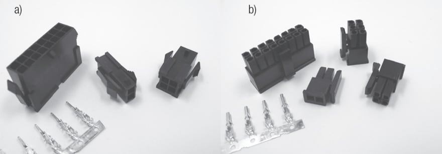
Another safety related impact on connector housing design is to provide barriers around the contacts to prevent inadvertent contact of external conductors or body parts, primarily fingers, to the hot side of the connector. Such protection is often referred to as “finger proofing”. Two modes of protection are common, recessing of contacts within the housing and silos surrounding the contacts. Examples of recessed and siloed contacts are provided in Figure 2.164a and b respectively.

Fig. 2.164: Recessed (a) and silloed (b) contacts

Current Considerations
The major concern relative to current, as noted, is Joule, I2R, heating. The I2 dependence indicates that higher current, i.e. power applications, are particularly sensitive to Joule heating and the associated temperature increases. As noted at several points in this text, temperature contributes to acceleration of many connector degradation mechanisms including corrosion, stress relaxation and, in worst case situations, degradation, including melting, of connector housings. Joule heating is particularly problematic in that it creates a positive feedback loop due to the positive temperature coefficient of resistivity of copper alloys. All of the components of resistance in a connector, permanent connection, separable interface and bulk resistances (Chapter I/1.3.3 The Electrical Interface: Contact Resistance) include the resistivity of contact spring material as a parameter. Thus all of these resistances increase with temperature. The increase in resistance results in an increase in Joule heating and the loop continues. A schematic illustration of the T-rise of a connector as a function of current is provided in Figure 2.165. Briefly, a T-rise measurement is generally made by attaching a thermocouple to the “hot spot” on the contact prior to testing. A selected current is applied, maintained and the temperature of the contact is measured periodically. The test is ended when the temperature has stabilized with time. IEC 60512-1 Part 3-1 Test 5a is a standard for T-rise testing.

Fig. 2.165: Temperature rise vs. time as function of current

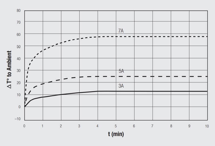
This consequence of Joule heating is addressed by application of temperature rise, T-rise, limits on connectors in power applications. One such commonly accepted T-rise limit, used to current rate connectors, is a 30 degree C increase in temperature. Power contact current rating will be discussed in the following sub-chapter.

It must be noted that PCB traces may greatly affect temperature rise in Wire To Board applications therefore any general comment must always be proof checked in real conditions/applications.

Two aspects of power contact/connector applications will be reviewed; contact/connector current rating and the distribution of current within an electronic system. Two approaches to current distribution will be discussed, the use of dedicated high current contacts and the use of multiple lower current capacity contacts in parallel in a connector housing.

Related

Source: Wurth elektronik

Recent Posts

Non-Magnetic Interconnects

23.4.2025
14

10 Tips for Ensuring Reliability of Discrete Wire Assemblies

20.2.2025
50

Polymer Materials and Processing

31.1.2025
35

Basic PCB Technology Overview

17.12.2024
15

What is RF Connector

17.12.2024
7

Creepage and Clearance of Connector

16.10.2023
12

Microwave Multi Line Connectors Mounting and Handling Precautions

17.12.2024
2

BASIC PCB Design Rules – Layout

17.12.2024
21

MEMR RF Relay for Space Compact Redundancy Ring

17.12.2024
2

Connector Temperature Rise and Derating

13.1.2023
12

Upcoming Events

May 28
16:00 - 17:00 CEST

Power Over Data Line

View Calendar

Popular Posts

  • Boost Converter Design and Calculation

    0 shares
    Share 0 Tweet 0
  • Buck Converter Design and Calculation

    0 shares
    Share 0 Tweet 0
  • Flyback Converter Design and Calculation

    0 shares
    Share 0 Tweet 0
  • Inductor Resonances and its Impact to EMI

    0 shares
    Share 0 Tweet 0
  • What is a Dielectric Constant and DF of Plastic Materials?

    4 shares
    Share 4 Tweet 0
  • LLC Resonant Converter Design and Calculation

    0 shares
    Share 0 Tweet 0
  • Dual Active Bridge (DAB) Topology Explained

    0 shares
    Share 0 Tweet 0
  • MLCC Case Sizes Standards Explained

    0 shares
    Share 0 Tweet 0
  • Ripple Current and its Effects on the Performance of Capacitors

    3 shares
    Share 3 Tweet 0
  • DC-DC Converter Basic Characteristics and Formulas

    0 shares
    Share 0 Tweet 0

Newsletter Subscription


Passive Components Blog

© EPCI - Leading Passive Components Educational and Information Site

  • Home
  • Privacy Policy
  • EPCI Membership & Advertisement
  • About

No Result
View All Result
  • Home
  • Knowledge Blog
  • Premium Suppliers

© EPCI - Leading Passive Components Educational and Information Site

This website uses cookies. By continuing to use this website you are giving consent to cookies being used. Visit our Privacy and Cookie Policy.
Go to mobile version