Passive Components Blog
No Result
View All Result
  • Home
  • NewsFilter
    • All
    • Aerospace & Defence
    • Antenna
    • Applications
    • Automotive
    • Capacitors
    • Circuit Protection Devices
    • electro-mechanical news
    • Filters
    • Fuses
    • Inductors
    • Industrial
    • Integrated Passives
    • inter-connect news
    • Market & Supply Chain
    • Market Insights
    • Medical
    • Modelling and Simulation
    • New Materials & Supply
    • New Technologies
    • Non-linear Passives
    • Oscillators
    • Passive Sensors News
    • Resistors
    • RF & Microwave
    • Telecommunication
    • Weekly Digest

    TDK Releases Automotive Power-Over-Coax Inductor for Filters

    Advanced Conversion Announces Mass Production of 200C Film Capacitors

    VinaTech Supercapacitors: Enhancing Smart Meter Reliability and Efficiency

    Bourns Introduces New Automotive Grade BMS Signal Transformer

    Hirose Unveils Compact Waterproof Version of IEC-Compliant ix Industrial Connector

    YAGEO Releases High-Sensitivity Residual Current Detectors for Safer EV Charging

    Bourns Introduces 1206 Multilayer Common Mode Filters

    KYOCERA AVX Presents Chip Antennas for SiP Market

    Chinas MLCC Makers Reach 10% Market Share

    Trending Tags

    • Ripple Current
    • RF
    • Leakage Current
    • Tantalum vs Ceramic
    • Snubber
    • Low ESR
    • Feedthrough
    • Derating
    • Dielectric Constant
    • New Products
    • Market Reports
  • VideoFilter
    • All
    • Antenna videos
    • Capacitor videos
    • Circuit Protection Video
    • Filter videos
    • Fuse videos
    • Inductor videos
    • Inter-Connect Video
    • Non-linear passives videos
    • Oscillator videos
    • Passive sensors videos
    • Resistor videos

    Understanding Switched Capacitor Converters

    Coupled Inductors Circuit Model and Examples of its Applications

    Inductor Resonances and its Impact to EMI

    Highly Reliable Flex Rigid PCBs, Würth Elektronik Webinar

    Causes of Oscillations in Flyback Converters

    How to design a 60W Flyback Transformer

    Modeling and Simulation of Leakage Inductance

    Power Inductor Considerations for AI High Power Computing – Vishay Video

    Coupled Inductors in Multiphase Boost Converters

    Trending Tags

    • Capacitors explained
    • Inductors explained
    • Resistors explained
    • Filters explained
    • Application Video Guidelines
    • EMC
    • New Products
    • Ripple Current
    • Simulation
    • Tantalum vs Ceramic
  • Knowledge Blog
  • Suppliers
    • Who is Who
  • Events
No Result
View All Result
Passive Components Blog
No Result
View All Result

Q Factor Modelling; How Poles and Zeros Relate to Q Factor

30.11.2023
Reading Time: 2 mins read
A A

Knowles Precision Devices, recently released white paper based on Python Scipy.signal Toolbox to explore the theory behind poles and zeros and how these impact Q factor and filter performance.

Quality factor, or Q factor, is a common shorthand figure of merit (FOM) for RF filters. It’s typically expressed as the ratio of stored versus lost energy per oscillation cycle.

RelatedPosts

Knowles Extends Range and Performance of C0G MLCC Capacitors

Supercapacitors Benefits in Industrial Valve Fail-Safe Control Systems

RF Inductors Key Characteristics and Applications

Steepness of skirts, selectivity, and insertion loss are all specifications that can be described in terms of Q factor. While this FOM feels ubiquitous in RF, truly understanding how Q factor is determined and how it relates to other specifications is a complex endeavor because it’s contextual. 

Here are a few different ways we can situate our understanding of Q factor:

  • Bandpass Q Factor: Refers to the width of a filter
  • Component Q Factor: Addresses individual inductor or capacitor quality
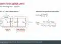
  • Pole Q Factor: Indicates the performance of different parts of a filter response; based on Pole Zero Plots

Pole Q factor is a particularly abstract context. Here, we look at poles and zeros in the complex plane. In theory, by moving the poles and zeros on the frequency axis, the slope gets steeper or shallower, impacting the sharpness of the filter. In practice, you can place zeros near frequencies you’d like to reject and poles near frequencies you’d like to pass. Ultimately, moving poles and zeros around on the plot crystallizes the filter response into the right shape for the customer.

Recently, we used Python Scipy.signal Toolbox to explore this and the theory behind poles and zeros. To follow along, read our white paper, Experimenting with Open-Source RF Analysis Tools to Better Understand How Poles and Zeros Relate to Q Factor.

Related

Source: Knowles Precision Devices

Recent Posts

Bourns Introduces 1206 Multilayer Common Mode Filters

16.6.2025
6

Bourns Releases New SMD Line Filter for Enhanced EMI Suppression

4.6.2025
16

TDK Expands 3-terminal Automotive SMD Chip Filters to 35V

4.6.2025
19

Kyocera Introducing SAW Filters for Implantable Medical and AED Applications

15.4.2025
29

Bourns Releases Automotive Grade Line Filters

1.4.2025
27

KYOCERA AVX Extends Small, High-Power, Thin-Film Band-Pass Filters

29.1.2025
36

EMC Challenges for High Speed Signal Immunity and Low EMI Power Delivery

17.1.2025
82

Interview with Murata President Norio Nakajima

16.1.2025
221

Top 10 Articles on Passive-Components in 2024

31.12.2024
260

Improving Common Mode Noise Reduction while Decreasing BOM

19.12.2024
182

Upcoming Events

Jun 24
17:00 - 18:00 CEST

Ultra-Compact and Efficient Switched-Capacitor Power Converters

Jul 23
13:00 - 14:00 CEST

PCB design for a Smartwatch

View Calendar

Popular Posts

  • Buck Converter Design and Calculation

    0 shares
    Share 0 Tweet 0
  • Boost Converter Design and Calculation

    0 shares
    Share 0 Tweet 0
  • Flyback Converter Design and Calculation

    0 shares
    Share 0 Tweet 0
  • What is a Dielectric Constant and DF of Plastic Materials?

    4 shares
    Share 4 Tweet 0
  • LLC Resonant Converter Design and Calculation

    0 shares
    Share 0 Tweet 0
  • Ripple Current and its Effects on the Performance of Capacitors

    3 shares
    Share 3 Tweet 0
  • How to Design an Inductor

    0 shares
    Share 0 Tweet 0
  • Dual Active Bridge (DAB) Topology Explained

    0 shares
    Share 0 Tweet 0
  • SEPIC Converter Design and Calculation

    0 shares
    Share 0 Tweet 0
  • Flying Capacitors Explained

    0 shares
    Share 0 Tweet 0

Newsletter Subscription


Passive Components Blog

© EPCI - Leading Passive Components Educational and Information Site

  • Home
  • Privacy Policy
  • EPCI Membership & Advertisement
  • About

No Result
View All Result
  • Home
  • Knowledge Blog
  • Premium Suppliers

© EPCI - Leading Passive Components Educational and Information Site

This website uses cookies. By continuing to use this website you are giving consent to cookies being used. Visit our Privacy and Cookie Policy.
Go to mobile version