According to article by Wu et al. from YAGEO researcher team in the International Journal of Applied Ceramic Technology, alloying nickel internal electrodes with small amounts of tin or indium significantly enhances the reliability of BaTiO3-based multilayer ceramic capacitors by strengthening interfacial and grain-boundary barrier layers.
Key Takeaways
- Alloying nickel internal electrodes with tin or indium enhances the reliability of BaTiO3-based multilayer ceramic capacitors (MLCCs).
- Ni–In electrodes provide the strongest improvement in mean time to failure (MTTF) as dielectric thickness increases, outperforming pure Ni and Ni–Sn.
- Ni–Sn improves reliability through a segregation layer forming a Schottky barrier but loses effectiveness with thicker dielectrics.
- Core-shell structures, influenced by Dy and In, are crucial for reducing oxygen-vacancy migration and enhancing dielectric performance.
- The study suggests optimizing In content and grain size for even better reliability in MLCCs, particularly for automotive and AI applications.
Introduction
This article investigates how alloying nickel (Ni) internal electrodes with tin (Sn) or indium (In) improves the long‑term reliability of BaTiO3-based multilayer ceramic capacitors (MLCCs), particularly for X7R automotive and AI data center applications that demand high capacitance, miniaturization and robust performance over wide temperature ranges. The study links electrical life test data with detailed microstructural analysis to clarify the role of interfacial Schottky barriers, grain boundary effects and core–shell grain structures in determining insulation resistance and mean time to failure (MTTF) as a function of dielectric layer thickness.
Extended Summary
Background and motivation
The rapid expansion of MLCC usage in automotive electronics and AI data centers has driven the need for BaTiO3-based devices with Ni internal electrodes that combine high capacitance, small case sizes and high reliability under harsh operating conditions. Conventional Ni-electrode MLCCs face challenges related to leakage current growth and long‑term insulation degradation, motivating strategies such as electrode alloying and rare-earth doping to stabilize the dielectric and interface.
Previous work showed that Ni–Sn internal electrodes increase the time to reach critical leakage current and improve MTTF, especially for thin dielectric layers, via enhancement of a Schottky barrier at the metal–semiconductor interface; however, this advantage diminishes as dielectric thickness increases. In parallel, rare‑earth dopants such as Dy are known to create core–shell grain structures in BaTiO3 that flatten the temperature dependence of permittivity and improve insulation by modifying defect chemistry and grain boundary behavior.
Experimental design and fabrication
The authors fabricated Ni, Ni–Sn and Ni–In MLCCs with X7R characteristics and 1005 case size (1.0 × 0.5 × 0.5 mm), varying the fired dielectric thickness from 0.8 to 8.0 µm while keeping chip geometry constant. The BaTiO3 dielectric powder was doped with Dy2O3, MgO, MnO2 and SiO2, tape cast, printed with Ni-based electrode pastes, stacked, fired at 1200 °C in a reducing atmosphere and re-oxidized, with Cu terminations added in a subsequent firing step.
Ni–Sn and Ni–In electrodes were produced by homogeneously mixing 1.0 wt.% SnO2 or In2O3 into the Ni paste; under the reducing sintering conditions, these oxides are reduced to metallic Sn and In and dissolve in Ni to form Ni–Sn and Ni–In alloys. Reliability was evaluated by highly accelerated life tests (HALT) at 140 °C using fields of 10 V/µm (8–80 V depending on thickness), with failure defined as reaching 1 mA leakage current; capacitance at 25 °C and dielectric constant (K value) were also measured.
HALT results and MTTF–thickness relationship
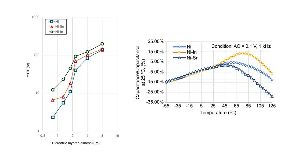
Table 1 and the log–log plot of MTTF vs. dielectric thickness show that for all three systems, MTTF increases as dielectric thickness increases from 0.8 to 8.0 µm, reflecting the larger number of grains, shell regions and grain boundaries contributing to overall insulation. At each thickness, Ni–In MLCCs exhibit the highest MTTF, followed by Ni–Sn and then pure Ni; for example, at 0.8 µm the MTTFs are 2.3 h (Ni), 6.7 h (Ni–Sn) and 12.2 h (Ni–In), while at 8.0 µm they reach 138 h (Ni), 144 h (Ni–Sn) and 198 h (Ni–In).
For Ni–Sn MLCCs, the reliability improvement is pronounced for thin dielectrics but gradually converges toward Ni performance as thickness increases, indicating that the dominant improvement mechanism is localized at the electrode/dielectric interface. In contrast, Ni–In MLCCs not only show strong enhancement at small thicknesses but also maintain a clear MTTF advantage even at 8 µm, implying additional contributions from within the dielectric layer, beyond the interface.
Role of dielectric constant and temperature characteristics
The dielectric constant K is consistently higher for Ni–Sn and Ni–In MLCCs compared with Ni, with Ni–In yielding the largest K across thicknesses (e.g., at 0.8 µm: K ≈ 2500 for Ni, 3050 for Ni–Sn and 3210 for Ni–In). These higher K values indicate that alloying elements influence the dielectric microstructure in ways that enhance effective permittivity, likely through changes in core–shell volume fractions and defect distributions.
Temperature dependence measurements for 1.3 µm samples show that Ni–Sn MLCCs slightly fall outside the X7R tolerance near 125 °C, with a depressed and shifted dielectric peak, consistent with Sn4+ occupying Ti4+ sites and lowering the Curie point. Ni–In MLCCs show a dielectric peak that shifts to higher temperatures and increases in magnitude compared with Ni, suggesting that In diffusion modifies the core–shell structure differently, possibly increasing the core volume fraction and altering phase transition behavior.
Interfacial segregation and Schottky barrier formation
Thermodynamic considerations using Ellingham diagrams indicate that both Sn and In have a stronger tendency to oxidize than Ni over a wide temperature range, with In being particularly prone to oxidation. This leads to segregation of Sn or In at the electrode/dielectric interface and their partial oxidation by capturing oxygen from adjacent BaTiO3, generating oxygen vacancies in the near-interface region and forming an n-type semiconductor zone that, when contacted by the metal electrode, produces a Schottky barrier.
Cs-STEM and EDS mapping for Ni–Sn MLCCs reveal a Sn-rich layer only a few nanometers thick at the interface, but little evidence of Sn segregation at grain boundaries, implying relatively homogeneous Sn diffusion into BaTiO3 grains. For Ni–In MLCCs, EDS shows strong In segregation at the electrode/dielectric interface and along grain boundaries, supporting the idea that In simultaneously contributes to an interfacial barrier and to grain boundary modifications deeper inside the dielectric.
Core–shell structure and Dy/In distribution
In all compositions the BaTiO3 grains exhibit a core–shell structure, where a Dy-containing shell surrounds a ferroelectric core, which helps meet X7R requirements and improves insulation. In Ni–In MLCCs, STEM-EDS mapping demonstrates that In coexists with Dy in the shell region and concentrates at grain boundaries as well as at the electrode interface, while the core remains relatively free of these dopants.
High‑resolution HAADF-STEM images of Ni–In samples show that the perovskite lattice continuity is preserved across the core–shell interface and up to the electrode interface, without obvious second-phase precipitates, implying that Dy and In occupy lattice A and/or B sites in BaTiO3. The contrast in HAADF intensity across the core–shell boundary, driven by the higher atomic numbers of Dy and In, clearly delineates the shell and confirms that these dopants are structurally incorporated rather than forming separate phases, which is important for maintaining dielectric performance.
Grain boundary barriers and defect chemistry
The authors relate their observations to established models of grain boundary double Schottky barriers in acceptor-doped BaTiO3 and SrTiO3, where space-charge depletion layers at grain boundaries impede oxygen-vacancy migration and suppress dielectric breakdown. In the Ni–In system, oxidized In is presumed to act as an acceptor, especially when occupying Ti4+ sites, thereby generating extrinsic oxygen vacancies that suppress the formation of intrinsic oxygen vacancies and reduce free electron concentration, lowering leakage current.
Because In is relatively large (In3+ radius 0.80 Å versus Ti4+ 0.605 Å), its diffusion and site occupation are likely concentrated at defect-rich interfaces and shells, similar to known impurity segregation phenomena in internal boundary layer capacitors. If In preferentially occupies Ti sites, Dy will preferentially occupy Ba sites, and the resulting negatively charged Ba vacancies can trap positively charged oxygen vacancies, further limiting their migration toward grain boundaries and preventing local accumulation that would trigger breakdown.
4-RC equivalent circuit perspective
Using a previously proposed 4‑RC equivalent circuit for rare‑earth‑doped X7R Ni‑electrode MLCCs, the dielectric layer is modeled as four serial RC elements: core, shell, grain boundary and electrode/dielectric interface. In this framework, the interfacial resistance contribution is thickness‑independent, whereas the resistances of the core, shell and grain boundaries scale with dielectric thickness due to the increased number of grains and boundaries.
The Ni–Sn system mainly improves the interfacial RC element, which explains why its relative benefit fades at larger thickness when the bulk and grain boundary contributions dominate. Ni–In, in contrast, simultaneously increases the resistance of the interface, grain boundaries and shell regions via In diffusion and acceptor behavior, so that the reliability improvement persists even as dielectric thickness grows.
Microstructural integrity and electrode continuity
Cross‑sectional SEM images confirm that all three MLCC types maintain high internal electrode continuity: approximately 98% for Ni, 97% for Ni–Sn and 96% for Ni–In at 1.3 µm dielectric thickness. These small differences in continuity are attributed to the diffusion of Sn and In but are judged insufficient to dominate MTTF behavior, supporting the conclusion that electrical reliability is governed primarily by interfacial and bulk defect structures rather than gross electrode discontinuities.
The authors also emphasize that electrode flatness and continuity remain crucial for avoiding local electric‑field intensification, but within the studied range, alloying does not significantly compromise these mechanical and geometric aspects.
Conclusion
The study demonstrates that alloying Ni internal electrodes with small amounts of Sn or In effectively improves the long‑term reliability of BaTiO3-based X7R MLCCs, with Ni–In providing the most robust enhancement across a wide range of dielectric thicknesses. Ni–Sn primarily strengthens the Schottky barrier at the electrode/dielectric interface, giving strong benefits for thin dielectrics but limited additional gains for thicker layers, whereas Ni–In combines interfacial barrier formation with grain boundary barrier layers and intragranular acceptor regions in the Dy/In‑modified shell of core–shell BaTiO3 grains.
As a result, Ni–In MLCCs exhibit higher MTTF and dielectric constants while maintaining appropriate temperature characteristics, and their reliability improvement continues as the dielectric layer becomes thicker. The authors suggest that further optimization of In content, BaTiO3 grain size and shell continuity could yield even more reliable Ni–In MLCCs for demanding automotive and AI‑related applications.
Read the full article:
Marklaw Wu, I-kung Cheng, Hiroaki Matsumoto, Masayuki Fujimoto, “Reliability improvement in BaTiO3-based multilayer ceramic capacitors by incorporating alloying of nickel internal electrodes” https://doi.org/10.1111/ijac.70092