Passive Components Blog
No Result
View All Result
  • Home
  • NewsFilter
    • All
    • Aerospace & Defence
    • Antenna
    • Applications
    • Automotive
    • Capacitors
    • Circuit Protection Devices
    • electro-mechanical news
    • Filters
    • Fuses
    • Inductors
    • Industrial
    • Integrated Passives
    • inter-connect news
    • Market & Supply Chain
    • Market Insights
    • Medical
    • Modelling and Simulation
    • New Materials & Supply
    • New Technologies
    • Non-linear Passives
    • Oscillators
    • Passive Sensors News
    • Resistors
    • RF & Microwave
    • Telecommunication
    • Weekly Digest

    Samtec Expands Connector Severe Environment Testing Offering

    Silicon Capacitors Market: Shaping the Foundation for Next-Gen Miniaturization Electronics

    YAGEO Releases Compact Coupled Inductors for High-Density VR Designs

    Enhancing Energy Density in Nanocomposite Dielectric Capacitors

    Advances in the Environmental Performance of Polymer Capacitors

    Vishay Releases DLA Tantalum Polymer Capacitors for Military and Aerospace

    Vishay Expanded Inductor Portfolio With More Than 2000 Stock Items 

    Paumanok Releases Capacitor Foils Market Report 2025-2030

    Modelithics Welcomes CapV as a Sponsoring MVP

    Trending Tags

    • Ripple Current
    • RF
    • Leakage Current
    • Tantalum vs Ceramic
    • Snubber
    • Low ESR
    • Feedthrough
    • Derating
    • Dielectric Constant
    • New Products
    • Market Reports
  • VideoFilter
    • All
    • Antenna videos
    • Capacitor videos
    • Circuit Protection Video
    • Filter videos
    • Fuse videos
    • Inductor videos
    • Inter-Connect Video
    • Non-linear passives videos
    • Oscillator videos
    • Passive sensors videos
    • Resistor videos

    Connector PCB Design Challenges

    Efficient Power Converters: Duty Cycle vs Conduction Losses

    Ripple Steering in Coupled Inductors: SEPIC Case

    SEPIC Converter with Coupled and Uncoupled Inductors

    Coupled Inductors in SEPIC versus Flyback Converters

    Non-Linear MLCC Class II Capacitor Measurements Challenges

    Percolation Phenomenon and Reliability of Molded Power Inductors in DC/DC converters

    Root Causes and Effects of DC Bias and AC in Ceramic Capacitors

    How to Calculate the Output Capacitor for a Switching Power Supply

    Trending Tags

    • Capacitors explained
    • Inductors explained
    • Resistors explained
    • Filters explained
    • Application Video Guidelines
    • EMC
    • New Products
    • Ripple Current
    • Simulation
    • Tantalum vs Ceramic
  • Knowledge Blog
  • Suppliers
    • Who is Who
  • Events
No Result
View All Result
Passive Components Blog
No Result
View All Result

Resistors Stability Prediction

2.9.2022
Reading Time: 6 mins read
A A

Learn about the aging behavior of resistors using temperature calculations and the Arrhenius equation to understand resistor drift and resistors stability in article written by Dr. Steve Arar and published by All About Circuits.

Aging Prediction—Resistor Drift Due to Aging

To begin with, let’s remember that the value of a resistor changes with time. In many circuits, only a gross level of precision is required and the resistor aging might not be a serious issue. However, certain precision applications require resistors with a long-term drift as low as a few parts per million over the specified lifetime.

RelatedPosts

Vishay Releases DLA Tantalum Polymer Capacitors for Military and Aerospace

Vishay Expanded Inductor Portfolio With More Than 2000 Stock Items 

How to Manage Supercapacitors Leakage Current and Self Discharge 

Therefore, it is important to develop aging prediction models with sufficient accuracy to ensure that the employed precision resistors maintain the specified precision over the entire lifetime of the system. One company, Vishay, suggests using the following equation (Equation 1) to calculate the long-term variation of a thin-film resistor:
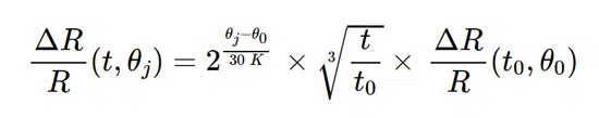
Eq.1. Resistance ageing drift

where

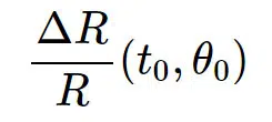
  • Is the reference drift of the resistor at the reference time t0t0 and temperature θ0θ0.
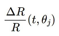
  • Is the drift value after the desired operating time of the resistor, t, at temperature θjθj.

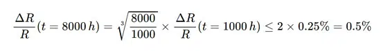
Equation 1 shows that raising the resistor’s operating temperature by 30 °K increases its long-term drift by a factor of 2. Additionally, the drift increases with the cube root of the operation time. For example, if the 1000-hour drift of the resistor at 125 °C is less than 0.25%, the resistor drifts after 8000 hours of operation at the same temperature (θj=θ0) is estimated by:

Arrhenius Equation for Resistor Aging Prediction

In Equation 1, the term that takes the temperature dependence into account is derived from the Arrhenius rate law which is also repeated below as Equation 2:

Eq.2. Arrhenius equation

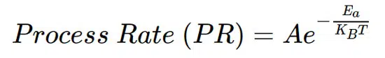
This equation specifies how the speed of a reaction changes with temperature in Kelvin (T). According to Vishay, the aging process of both thin-film and foil resistors obeys the Arrhenius equation.

Figure 1 shows the aging data of identical foil resistors at different temperatures.

Figure 1. Image used courtesy of Vishay

In this figure, the natural logarithm of the standard deviation of the resistors’ drift distribution (Ln(DSD)) is plotted against 1000/T.

Note that a straight line can be fit to these data points. This is consistent with the Arrhenius equation, which can be expressed as:

This equation shows that the plot of Ln(PR) versus 1/T is a straight line when a reaction obeys the Arrhenius equation.

Since this relationship holds true for the data points in Figure 1, we can conclude that the aging process of these resistors obeys the Arrhenius law.

Estimate Resistor Temperature – Improving Long-term Resistor Stability

Based on Equation 1, keeping the resistor at a lower temperature can reduce its drift with time. The remaining question is, how can we keep the resistor cooler?

The θ terms in Equation 1 refer to the resistor temperature rather than the ambient temperature. The resistor temperature (θ Resistor) can be estimated by the following equation:
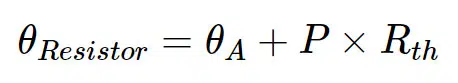
Where:

  • θA is the ambient temperature
  • Rth is the thermal resistance of the resistor
  • P is the power dissipated in the resistor

This equation shows that, in addition to the ambient temperature, the heat dissipated in the resistor and the thermal resistance value can affect the resistor temperature.

For the resistor to run cooler, we can limit the power dissipated in the resistor if possible. Besides, changing the characteristics of the PC board, such as the trace density and the number of the power/ground planes, can change the value of the effective thermal resistance of the system. This change is because the PC board acts as a heatsink soldered to the resistor. A more efficient heatsink or use of SMD thermal conductors can improve heat transfer and keep the circuit components, including the precision resistors, cooler.

Adjusting different design parameters, we can attempt to keep the resistor temperature below a typical maximum value of 85 °C to achieve improved long-term stability.

It is also worth mentioning that operating a resistor at power levels higher than the nominal value can lead to a long-term drift larger than that predicted by the Arrhenius-based equations. Above the rated power, some hot spots can appear in parts of the resistive material where the aging process is accelerated. This can lead to a drift value larger than that predicted by the average temperature of the resistor.

Related

Source: All About Circuits

Recent Posts

Silicon Capacitors Market: Shaping the Foundation for Next-Gen Miniaturization Electronics

10.10.2025
4

Enhancing Energy Density in Nanocomposite Dielectric Capacitors

9.10.2025
13

Advances in the Environmental Performance of Polymer Capacitors

8.10.2025
30

Benefits of Tantalum Powder Stress–Strain Curve Evaluation vs Conventional Wet Test

3.10.2025
23

Electrolyte Selection and Performance in Supercapacitors

3.10.2025
28

Connector PCB Design Challenges

3.10.2025
32

Researchers Demonstrated High Energy Ceramic Capacitors Stable in Wide Temperature Range

2.10.2025
24

Stackpole Offers High Voltage Plate Resistors up to 40KV

2.10.2025
22

How to Manage Supercapacitors Leakage Current and Self Discharge 

1.10.2025
44

Experimental Evaluation of Wear Failures in SMD Inductors

1.10.2025
41

Upcoming Events

Oct 14
16:00 - 17:00 CEST

Smart Sensors, Smarter AI: Building Reliable Edge Systems

Oct 17
12:00 - 14:00 EDT

External Visual Inspection per MIL-STD-883 TM 2009

Oct 20
October 20 - October 23

Digital WE Days 2025 – Virtual Conference

Oct 21
October 21 @ 12:00 - October 23 @ 14:15 EDT

Space and Military Standards for Hybrids and RF Microwave Modules

Oct 28
8:00 - 15:00 CET

Power Up Your Design: SN6507 and the Ready-to-Use Development Kit

View Calendar

Popular Posts

  • Buck Converter Design and Calculation

    0 shares
    Share 0 Tweet 0
  • Boost Converter Design and Calculation

    0 shares
    Share 0 Tweet 0
  • Flyback Converter Design and Calculation

    0 shares
    Share 0 Tweet 0
  • LLC Resonant Converter Design and Calculation

    0 shares
    Share 0 Tweet 0
  • What is a Dielectric Constant and DF of Plastic Materials?

    4 shares
    Share 4 Tweet 0
  • SEPIC Converter Design and Calculation

    0 shares
    Share 0 Tweet 0
  • Dual Active Bridge (DAB) Topology Explained

    0 shares
    Share 0 Tweet 0
  • Ripple Current and its Effects on the Performance of Capacitors

    3 shares
    Share 3 Tweet 0
  • MLCC and Ceramic Capacitors

    0 shares
    Share 0 Tweet 0
  • Flying Capacitors Explained

    0 shares
    Share 0 Tweet 0

Newsletter Subscription


Passive Components Blog

© EPCI - Leading Passive Components Educational and Information Site

  • Home
  • Privacy Policy
  • EPCI Membership & Advertisement
  • About

No Result
View All Result
  • Home
  • Knowledge Blog
  • Premium Suppliers

© EPCI - Leading Passive Components Educational and Information Site

This website uses cookies. By continuing to use this website you are giving consent to cookies being used. Visit our Privacy and Cookie Policy.
Go to mobile version